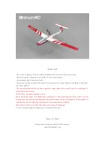
Assembly Instructions Manual для модели MinimumRC ASG-32 доступен для скачивания бесплатно на нашем сайте. Этот руководство поможет вам легко и правильно собрать вашу модель. Скачайте его прямо сейчас с {ваш веб-сайт} и начните собирать свою ASG-32!
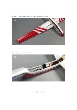
30. Take two magnets and two magnet mounting seats.
31. Fix the magnet to the wooden mounting base with 502 glue.
32. Install the fuselage magnet seat.
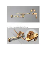
Страница 1: ...parts 502 glue will cause serious corrosion to foam parts 2 Please wait for the glue to dry and solidify in each installation step before the next installation 3 Please avoid using flame to heat the heat shrinkable tube on the model Electric iron shall be used for heating 4 Please use razor blade to remove the parts from the plate Do not tear the parts by force 1 Fuselage internals ...
Страница 2: ...2 Bond the inner structure of the fuselage with 502 glue Please pay attention to the opening direction of the servo base ...
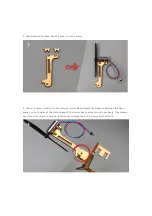
Страница 3: ...1 2x6mm screw to fix the turnover motor base Adjust the distance between the fixed pieces on both sides of the motor base till the motor base can be turned over freely If necessary sand the motor base to reduce its thickness to make the turning movement smooth ...
Страница 4: ...ceiver with your transmitter to make the servos return to their neutral point Test whether the servos are working normally and install the servo arms according to the position shown in the picture use screws to fix the servos on the servo base from the top Note Please make sure that the servos have been tested and installed in strict accordance with the following picture After assembling the model...
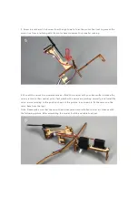
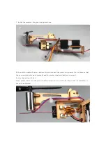
Страница 5: ...d motor and connect the receiver to power for test Ensure that the servos and motor work normally and the motor rotation direction is correct Secure the cable with ties Note please make sure the motor rotation direction is correct After the model is assembled it cannot be adjusted ...
Страница 6: ...inner structure with the right panel of the fuselage Note the bottom of inner structure red circles should be 2mm away from the edge 10 Use the end of a carbon fiber rod to score through the half cut line of the tail surface ...
Страница 7: ... can be bent before bonding In strict accordance with the A B C D E F sequence installation can ensure the accurate position of the fuselage side strips The fuselage side strips should be aligned with the fuselage side plate contour which is helpful to the model aesthetics 12 The installation of fuselage side plate is completed as shown in the figure Take 200 mm conduit and two duct seats for elev...
Страница 8: ...etween the seat and the conduit hole on the side plate is about 30mm 14 As shown in the figure paste a duct seat on the right side of the vertical tail This guide socket is used to fix the end of elevator drive pipe The blue curve in the figure shows the route of elevator conduit pipe and steel wire ...
Страница 9: ...ide the fuselage and the two ends of the conduit pass through the two conduit holes on the right side of the fuselage Left end of the guide pipe extends out of the fuselage by 5mm 16 Glue the end of the duct to the duct seat on the vertical tail ...
Страница 10: ... Take one 170mm conduit and one duct base Paste the duct base inside the left side of the fuselage 30mm away from the duct hole 18 Glue the conduit to the conduit base on the left side of the fuselage both of the ends of the conduit pass through the conduit hole ...
Страница 11: ...through the holes on the fuselage and the length of the two ends is 5mm 20 Close the fuselage on both sides and glue Pay attention to keep the fuselage edge aligned with the fuselage side panel edge Check to eliminate the distortion of the vertical tail ...
Страница 12: ...de of the fuselage The sticker acts as a hinge for the hatch opening and closing so the sticker at the nose red circle needs to be reinforced with glue to increase reliability 22 Install the horizontal tail with the scribe face down ...
Страница 13: ...rol horn The elevator control horn is special in shape and it should be pointed to the tail of the aircraft during installation 24 Cut 4 pieces of 5mm long transparent heat shrinkable tube to connect the steel wire and the pushrod clips ...
Страница 14: ... the conduit on the fuselage The steel wire is used for elevator drive and the shorter one is used for rudder drive 26 Install the pushrod clip on the rudder control horn and connect it with the wire by using a heat shrinkable tube ...
Страница 15: ...onnect elevator control horn pushrod clip and steel wire 28 Connect the pushrod clip steel wire and servo arm 29 Cut off the connection points on the side of the hatch cover so that it can be lifted forward ...
Страница 16: ...30 Take two magnets and two magnet mounting seats 31 Fix the magnet to the wooden mounting base with 502 glue 32 Install the fuselage magnet seat ...
Страница 17: ...33 Install the hatch magnet seat 34 Use the end of a carbon fiber rod to score through the half cut line of the wing surface 35 Install wings and wing tips ...
Страница 18: ...36 Attach a 250mm carbon fiber rod on each bottom side of wings 37 The battery is placed in the cabin Assembly complete ...
Страница 19: ...rcraft enters into stall state it will produce bow torque Performance the plane appears to bow Scene the initial speed of throwing off is insufficient or the flight speed of the aircraft is too low Coping style improve the initial speed of hand throw take off and cooperate with the elevator in time Before the first flight test the elevator can be adjusted up slightly When the aircraft is out of th...