Technical support - [email protected]
© 2009 Copyright Minicom Advanced Systems. All rights reserved.
5UM20184 V1.1 9/09
Smart 216 / 232 IP- Quick Start Guide
1. Introduction
To take advantage of the full range of features, we recommend you read the
softcopy User Guide after performing the Quick Start procedure. It’s in PDF format
on the supplied CD or on our website www.minicom.com in the Support section.
All references throughout this guide to the Smart 216 IP refer equally to the Smart
232 IP. The two units are functionally the same. The Smart 216 IP has 16 Server
ports and the Smart 232 IP has 32 Server ports.
The Smart 216 IP extends your KVM (keyboard, video, and mouse) from any
computer or server over TCP/IP via LAN, WAN or Internet connection. Now 2
remote users can control, monitor and manage up to 16 remote (PS/2, USB) servers
simultaneously from wherever they are, inside or outside the organization.
Simultaneously 1 local user can also access the servers. Simultaneously 2 more
remote users can operate serial devices such as routers or managed network
switches. Alternatively, 1 more user can use a PDU.
2. Key features
BIOS level control
to any server’s brand and model, regardless of the server
condition and network connectivity, covering the entire spectrum of crash
scenarios.
Compatible
with all major operating systems. Supports many hardware and
software configurations for the remote client and the Target server computers, as
well as the KVM switch in use
SMART 216 / 232 IP
1
Web-based control -
Browser Control to a Target server, from any location via
secured standard IP connection.
Security
- Supports the highest security standards for encryption (256 bit SSL and
HTTPS) and authentication for remote user and advanced OSD management with
multi-layer security for local user.
Centralized Management
-
Can be controlled by the Minicom’s Centralized
Management systems – AccessIT and KVM.net II.
Seamless power control
– with Minicom’s Serial Remote Power Switch.
3. System components
The system consists of:
•
1 Smart 216 IP (p/n 1SU70036) or 1 Smart 232 IP (p/n 1SU70037)
•
Rack mounting set (p/n 5AC20247)
•
ROCS - PS/2, USB
4. Compatibility
The Smart 216 IP is compatible with:
•
PS/2 and USB computers/servers
•
VGA, SVGA, or XGA monitors
•
Windows, Linux, UNIX and other major operating systems
5. Terminology
Below are some terms and their meanings used in this guide.
Term Meaning
Target server
The computers/servers that are accessed remotely via the Smart 216
/ 232 IP.
Client computer
The PC running a remote Smart 216 / 232 IP session
Remote session
The process of remotely accessing and controlling Target servers
connected to Smart 216 / 232 IP from a user workstation
6. Client computer operating system
Windows 2000 or higher, with Firefox 3 or Internet Explorer 6.0 or later version.
Linux with Firefox 3.
QUICK START GUIDE
2
7. The Smart 216 IP unit
Figure 1 illustrates the front panel of the Smart 216 IP.
MINIC
O
M
Power
Remote
Link
SMART 216 IP
2
1
Figure 1 Smart 216 IP front panel
7.1 LED and button table
LED Function
Power
Power Indicator
Link
Unit is connected to the network
Remote 1 & 2
Illuminates when a remote session is active
Power
POWER
100-240 VAC 50/60 Hz
Server ports
I
0
1
2
3
4
5
6
7
8
Keyboard
Mouse
Monitor
LOCAL USER
LAN (Ethernet)
port
LAN
SERIAL 1
Serial 1 port
10
11
12
13
14
15
16
9
SERIAL 2
SERVER
Serial 2 port
Figure 2 Smart 216 IP ports
7.2 Connector table
Connector Function
Console KVM
Connect a keyboard, video and mouse to operate the Smart 216 IP locally
Serial 1
Connect any Serial device. Note! Minicom’s Serial Remote Power Switch
must be connected to Serial 1
Serial 2
Connect any Serial device.
LAN
Connect to 10/100 Mbit Ethernet. Yellow Led illuminates when connected
to LAN. Green LED illuminates when a remote session is in progress
Server ports
Connect to servers via ROCs
8. Pre-installation guidelines
•
Place cables away from fluorescent lights, air conditioners, and machines that
are likely to generate electrical noise
•
Place the Smart 216 IP on a flat, clean and dry surface
•
The Smart 216 IP is not intended for connection to exposed outdoor lines
•
Ensure that the maximum distance between each computer and the Smart 216
IP, does not exceed 30m/100ft for ROCs.
SMART 216 / 232 IP
3
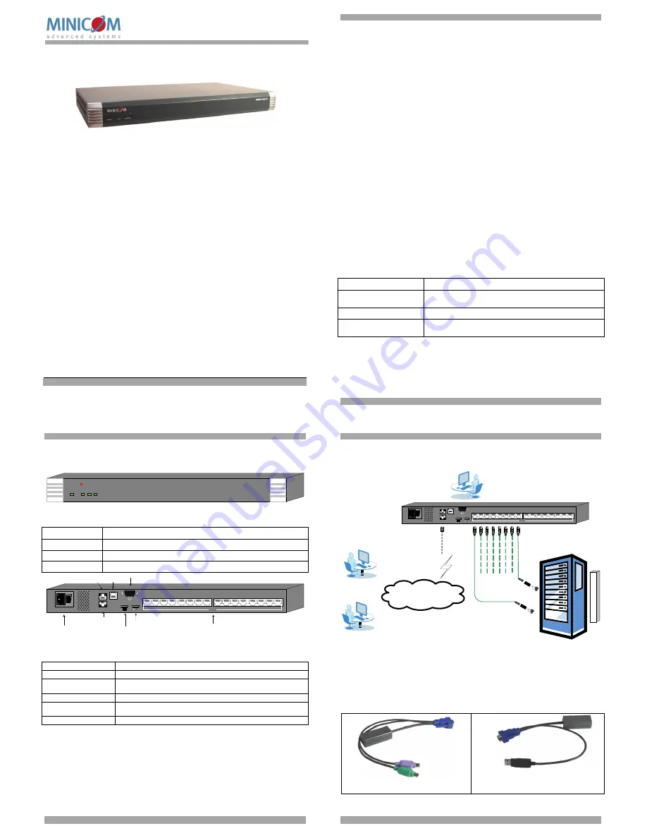
9. Connecting the system
Figure 3 illustrates the Smart 216 IP system overview.
User 2 over IP
Internet / VPN / LAN
To servers
To LAN port
ROCs
POWER
100-240 VAC 50/60 Hz
I
0
1
2
3
4
5
6
7
8
LOCAL USER
LAN
SERIAL 1
10
11
12
13
14
15
16
9
SERIAL 2
SERVER
User 1 over IP
Local User
PDU
Figure 3 Smart 216 IP system overview
9.1 The ROCs
Each computer/server is directly connected to the Smart 216 IP via the appropriate
ROC using CAT5 cable in a star configuration. No external power is needed at the
remote ROCs. The ROCs draw their power from the computer’s keyboard port
(ROC PS/2) or from the USB port (ROC USB). The figures below illustrate the
ROC PS/2 and ROC USB.
To computer’s
keyboard port
To computer’s
mouse port
To computer’s
Video card
Figure 4 ROC PS/2
To computer’s
USB Port
To computer’s
Video Card
Figure 5 ROC USB