background image


User Manual of DH-300/400 Full Automatic Soldering Robot


Precautions 

Please read the following safety precautions to prevent this product or any other 
products  connected  with  it  from  being  damaged.  In  order  to  avoid  possible 
dangers, this product can be only used in the specified range. 


Use  proper  power  cord:

  Only  use  the  dedicated  power  cord  provided 

with this product. Before use, check the power cord to confirm there is no 
damage or electric leakage.


Product  grounding: 

This  product  is  grounded  through  the  power  cord. 

Use the power socket with reliable grounding wire.


Do not pull out or insert the serial port connected with the computer 
and the programmer when the machine is powered on. 


Please keep the product surface clean and dry, and do not operate it in 
an environment which is humid or has corrosive gas. 


Do not put articles on the machine. 


Please turn off the power supply after use. 


The  size  of  components  to  be  welded  shall  meet  the movement  index 
of this product. 


Do not use the serial port line of the handheld programmer to connect 
PC; otherwise PC may be damaged. 


Do  not  disassemble  the  machine  without  authorization  to  avoid  the 
risk of electrical shock. 


Содержание DH-300

Страница 1: ...tion and Commissioning 8 2 1 Unpacking 8 2 2 Assembling 9 2 3 Installation and Adjustment of Tin Wire 20 2 4 Adjustment of Soldering Bit Mechanism 23 2 5 Equipment Commissioning 25 3 Basic Operation 2...

Страница 2: ...t is grounded through the power cord Use the power socket with reliable grounding wire Do not pull out or insert the serial port connected with the computer and the programmer when the machine is powe...

Страница 3: ...gidity and low center of gravity and has good movement performance and extremely low noise During movement the machine is stable and is convenient to download the motion parameters AUTOCAD data file c...

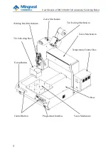
Страница 4: ...Full Automatic Soldering Robot 4 Y axis Mechanism Welding Head Mechanism Base Z axis Mechanism X axis Mechanism E stop Button Programmer Interface Tin Collecting Box Tin Feeding Mechanism Temperature...

Страница 5: ...rogrammer and the track storage number is up to 120 7 Welding time and track running speed can be adjusted by programming 8 With three axis fine tuning operation teaching point coordinates are more ac...

Страница 6: ...aximum load Worktable 8Kg Operating speed 80mm s Z axis 2 5Kg Operating speed 80mm s 8 Overall dimensions 620mm 600mm 700mm L W H 9 Weight 61Kg 10 Task storage number 120 Parameter Requirements of Wel...

Страница 7: ...ing Robot 7 1 3 Operating Environment 1 Application range of supply voltage 220V AC fluctuation range 10 15 frequency 50 1 Hz 2 Ambient temperature 0 40 C 3 Relative humidity 20 90 no condensation 4 P...

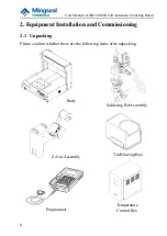
Страница 8: ...Soldering Robot 8 2 Equipment Installation and Commissioning 2 1 Unpacking Please confirm whether there are the following items after unpacking Z Axis Assembly Soldering Bit Assembly Body Tin Blowing...

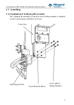
Страница 9: ...2 2 Assembling 2 2 1 Installation of Soldering Bit Assembly The soldering bit assembly of the three axis welding machine is installed on the Z direction movable block of Z axis Screw M4x12 Spring Was...

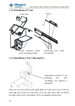
Страница 10: ...plane of Y axis outer cover fix the tin collecting box on the two screw holes of Y axis outer cover with two M3X8 hexagon socket screws and washers with corresponding specification M4x16 hexagon socke...

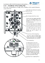
Страница 11: ...leeve seat shall be adjusted to the leftmost side and the adjusting base shall be adjusted to the uppermost side Tin Blocking Detecting Piece The tin blocking detecting piece shall be close to the tin...

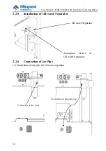
Страница 12: ...ring Robot 12 2 2 5 Installation of Oil water Separator 2 2 6 Connection of Air Pipe 1 Connection of air pipe for oil water separator Connection of 6mm air pipe Connection of air source Oil water Sepa...

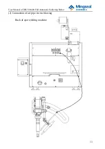
Страница 13: ...User Manual of DH 300 400 Full Automatic Soldering Robot 13 2 Connection of air pipe for tin blowing Back of spot welding machine...

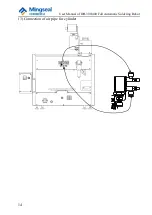
Страница 14: ...User Manual of DH 300 400 Full Automatic Soldering Robot 14 3 Connection of air pipe for cylinder...

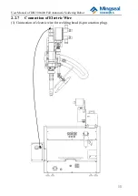
Страница 15: ...User Manual of DH 300 400 Full Automatic Soldering Robot 15 2 2 7 Connection of Electric Wire 1 Connection of electric wire for welding head 6 pin aviation plug...

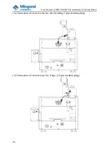
Страница 16: ...User Manual of DH 300 400 Full Automatic Soldering Robot 16 2 Connection of electric wire for wire feeding 7 pin aviation plug 3 Connection of electric wire for Z axis 12 pin aviation plug...

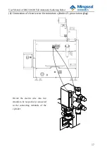
Страница 17: ...0 Full Automatic Soldering Robot 17 4 Connection of electric wire for miniature cylinder 5 pin aviation plug Divide the electric wire into two strands to be respectively connected to the connecting te...

Страница 18: ...User Manual of DH 300 400 Full Automatic Soldering Robot 18 5 Connection of programmer interface...

Страница 19: ...User Manual of DH 300 400 Full Automatic Soldering Robot 19 6 Power supply connection and switch Foot Switch Power Interface Power Switch...

Страница 20: ...hrough the guide sleeve opening at the top of the tin feeder lift the handle to let the tin wire pass through the clearance of friction wheel and reach the interior of the wire leading opening at the...

Страница 21: ...1 2mm is used it is only necessary to adjust the clearance of tin feeding wheel to the minimum clearance When the tin wire of 1 4mm or 1 5mm is used the adjustment method is the same as that of the t...

Страница 22: ...ery small between the blade and the tin wire 3 Service life of blade It is predicted that the service life of the blade is about 1 year according to the material properties of the blade and the force...

Страница 23: ...ing point of soldering bit and adjusting the soldering pencil rod anticlockwise in the front view direction as shown in the following figure When two M4 hexagon socket cap screws are loosened the sold...

Страница 24: ...outlet to the distance required by the tip of soldering bit and then lock 7 It is suggested that the distance control should not be less than 8mm 5 Loosen 9 to slide and rotate 10 in the hole and adj...

Страница 25: ...sk number default 0 is displayed on the nixie tube In this state communication can be made with PC or the handheld programmer and tasks can be downloaded onto the slave computer after graphic teaching...

Страница 26: ...Basic Operation 3 The metal buttons marked with X X Y Y Z and Z are used to set the function number and parameters in the function control modify the current reference point values of X Y and Z axes...

Страница 27: ...Reset button once to pause the running task at any time After the task is paused the task number displayed on the nixie tube starts flashing To continue to run this task please press Run button To res...

Страница 28: ...tion is completed after OK button is pressed Task selection is completed 3 1 4 Running This function realizes the welding startup of the confirmed tasks Operation process After task selection is compl...

Страница 29: ...it error will be prompted The solution is to adjust the reference point again Operation process Task selection Reference point The reference point is raised by a certain height from the starting point...

Страница 30: ...hether zero correction is performed after welding is finished each time Enter the function setting menu with the Function button and select the function option with X and X buttons 1 Zero correction s...

Страница 31: ...welding head stops at the last welding position after end of running each time and Y axis moves Y axis positioning distance Function 9 can be used to set Y axis positioning distance towards the direct...

Страница 32: ...tion setting operation Reset Cancel the current operation and return 3 Adjustment unit setting of reference point Operation process Function X Select the function No 3 OK Enter X X Y Y Z Z Adjust the...

Страница 33: ...point to the starting point so as to prevent the welding head from being damaged when the reference point is adjusted Operation process Function X Select the function No 4 OK Enter X and X Adjust the...

Страница 34: ...800 1 represents the minimum speed in mm s and 800 represents the maximum speed in mm s Wherein the increment of X button is 1mm s the increment of Y button is 10mm s and the increment of Z button is...

Страница 35: ...100mm s Display status of nixie tube Display the function item number Before adjustment After adjustment OK To execute the reset operation during function setting operation Reset Cancel the current o...

Страница 36: ...operation Reset Cancel the current operation and return 8 Setting of automatic delay operation i e when pressing Run or Pedal once the equipment will execute the automatic delay operation according t...

Страница 37: ...ry to press Reset button during the track operation process of the equipment Then the equipment exits the automatic operation status to execute the reset action After reset the setting of function num...

Страница 38: ...stment After adjustment Note To use this function the parameter of the function No 1 is set to 2 OK To execute the reset operation during function setting operation Reset Cancel the current operation...

Страница 39: ...ting operation Reset Cancel the current operation and return 12 Setting of automatic deceleration This function is reserved at present Operation process Function X Select the function No 12 OK Enter X...

Страница 40: ...task is 300 If the following is displayed after pressing OK One decimal point is displayed indicating that the counting of welding spots has undergone a cycle At this time the number of welding spots...

Страница 41: ...locking point to next operation point When tin blocking warning emerges during the task running press reset and then run button the system will move to the first operation point OK Function parameters...

Страница 42: ...after each soldering point drag soldering section the IO mouth OUT3 will output a rated time impulse and time unit is ms OK Functions parameters setting to do reset operation reset cancel the operatio...

Страница 43: ...ort time the time is 10 times of the rated time and unit is ms OK Function parameters setting to do reset operation reset cancel the operation and machine reset 17 Soldering points counting warning pa...

Страница 44: ...ation reset cancel and machine reset 18 Slant angle setting operation process function X select item No 18 OK Enter X X Y Y Z Z parameters setting Display status of nixie tube Function No display Init...

Страница 45: ...on distance OK 11 Deletion of current task OK 12 Setting of automatic deceleration OK 13 Counting function of welding spots corresponding to task OK Function 1 parameter X X Y Y Z Z 0 2 OK Function 2...

Страница 46: ...of DH 300 400 Full Automatic Soldering Robot 46 Reset Pedal Run Reset Note The serial port communication is valid only in the task selection menu namely it will be normal if being connected with the h...

Страница 47: ...utton to lift or drop the welding head cylinder 3 3 Temperature Control System 3 3 1 General Temperature Setting Note Confirm that the soldering station is in the temperature adjustable state enter th...

Страница 48: ...the condition that the heating element is not powered off please select this method Do not press SET but directly press or key to set the temperature to rise or fall by 1 C and the window displays the...

Страница 49: ...as that of General Temperature Setting After selecting the three digits of the password press SET key 5 If the temperature control system enters the normal operation state after the window displays th...

Страница 50: ...n the window displays It is necessary to enter the new password see the above steps 8 9 The password change is not successful until the passwords entered twice are the same When the window displays si...

Страница 51: ...With sleep and automatic shutdown 5 50 C 420 C With sleep and automatic shutdown 6 200 C 480 C With sleep and automatic shutdown 7 200 C 480 C With sleep and automatic shutdown 0 200 C 420 C Without...

Страница 52: ...state for 40 minutes the power supply of the welding head will be automatically cut off and the window will have no display The factory settings of the temperature control box is 6 namely without slee...

Страница 53: ...erformed the welding tip temperature shall not exceed 400 C Experimental results show that when the welding tip temperature exceeds 400 C the service life of the welding tip is greatly reduced Taking...

Страница 54: ...ion 5 When the welding tip is out of service new tin layer shall be added after cleaning to prevent it from being oxidized 3 3 6 Maintenance of Soldering Bit Inspection and cleaning method of solderin...

Страница 55: ...le when it is capable of working Low temperature can reduce the oxidization of the soldering bit and helps to weld the components 3 Flux with less activated rosin shall be used because high content ac...

Страница 56: ...eating core with a hole in the middle The heating core is very convenient to replace when being damaged Don t worry about wrong insertion See the real object for details For specific replacement of he...

Страница 57: ...User Manual of DH 300 400 Full Automatic Soldering Robot 57 Next loosen two M4 set screws on the soldering pencil rod and then screw off Plastic Nut Steel Sleeve Soldering Bit...

Страница 58: ...osen M4 screws not to be disengaged with the soldering pencil rod because M4 screws are used to compress the end cap of heating core and prevent it from being loosened Note In normal use condition the...

Страница 59: ...hall be paid by the user 3 4 Welding Example During programming pay attention to the setting of relevant welding parameters Take welding with pad specification of 1mm as shown in the following figure...

Страница 60: ...ad size If the pad is too small it is possible not to set them For example it is possible not to set them for the above pad Secondary tin feeding volume and secondary tin feeding speed Select the tin...

Страница 61: ...witch 2 Reset 3 Check whether the programmed task is correct If not correct please contact the after sales service department 2 E 002 Y axis over travel 1 The E stop switch is active 2 The photoelectr...

Страница 62: ...sk is not loaded and it is necessary to perform the operation related to the task 1 Perform the reset operation 2 Load the task select the task and then execute the running or reference point operatio...

Страница 63: ...t 12 E 402 Welding system not ready 1 When the task starts to run manual tin feeding return and blowing operations or vertical action of the cylinder are being performed 1 When pressing Run or Pedal t...

Страница 64: ...rostatic interference In this case it does not influence the normal use of the machine Such phenomenon can be solved by resetting the machine Phenomenon 3 After the machine is powered on Z axis is loc...

Страница 65: ...of the linear guide to slide up and down for several times Meanwhile it is possible to add the lubricating oil to the sliding block through its oil hole 2 X axis Remove the X axis middle baffle plate...

Страница 66: ...User Manual of DH 300 400 Full Automatic Soldering Robot 66 Z axis Enclosure Z axis Linear Guide X axis Middle Baffle Plate X axis Linear Guide...

Страница 67: ...our after sales service staff to maintain the machine on site 5 It is necessary to open the bottom box cover to remove the dust for the internal circuit boards and other components of the machine ever...

Страница 68: ...movement mechanism of soldering bit every two months Methods The linear guide can be seen from the side Blow away the dust on the surface of linear guide by high speed airstream and fill the lubricati...

Страница 69: ...ive and the volume of steel wire balls placed does not exceed one third of the whole tin collecting box 2 If the molten tin blown down overspreads the surface of the steel wire ball in use the steel w...

Отзывы: