

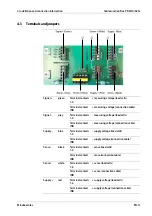
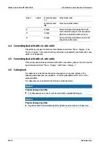


Terminal contacts
1–4
Screen (load cells)
Screen
yellow
Terminal contact
IND
Screen (connection cable)
J1
Jumper
J2
Jumper
Connects the load cell supply line to the
sense line. Both jumpers must be opened
when 6-wire load cell cables are used.
J3
Jumper
Connects the load cell cable screen to the
connection cable screen.
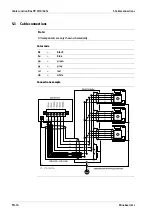
4.4 Connecting load cells with a 4-wire cable
Upon delivery, jumpers J1 and J2 are closed between terminals "Sense -/Supply -" and
"Sense +/"; this means that the junction box is prepared for load cells with 4-wire
cables; see Chapter
.
4.5 Connecting load cells with a 6-wire cable
If the junction box will be used for load cells with 6-wire cables, jumpers J1 and J2 must be
open between terminals "Sense -/Supply -" and "Sense +/."
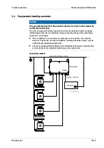
4.6 Cable gland
The cables have to be fed into the device via glands to ensure leak-tightness. The
following cable diameters are suitable: 8…13 mm for gland M20 and 4.5…6.5 mm for
cable gland M12.
The cable wires are connected to the terminals inside the device.
NOTICE
Property damage is possible.
If a cable gland is not used, it must be sealed with a supplied locking pin.
NOTICE
Property damage is possible.
Regularly check the fitted cable gland for tightness and re-tighten it, if necessary.
Cable Junction Box PR 6130/64Sa
4 Installation and connection information
EN-14
Minebea Intec


