background image

4. Device installation  | 4.3 - Hardware construction  | 43

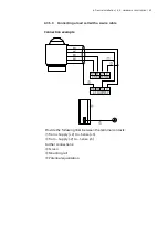
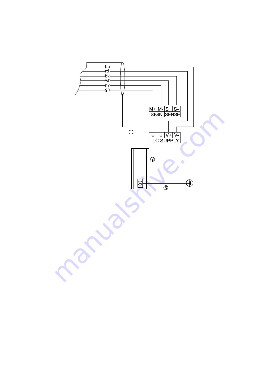
4.3.5.4  Connecting a load cell with a 6-wire cable

Connection example

 Screen

 Mounting rail

 Potential equalization

4.3.5.5  Connecting between 2 and  8 load cells (650 Ω) using a 6-wire 
connection cable

Connections are made via cable junction box PR 6130/.. using connection 
cable PR 6135/.. or PR 6136/... .

Recommendation

Install cable in steel pipe connected to a ground potential.

The distance between the measuring cables and the power cables should 
be at least 1 m.

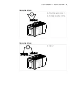
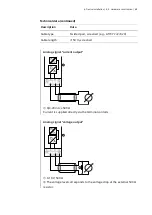
Load cell supply circuit

Load resistance of load cell circuit ≥75 Ω, e.g., 8 load cells of 650 Ω each

The supply voltage is fixed at U

DC

 = 5 V  and protected against short cir­

cuits.

For further technical data, see Chapter 

General technical data

.

Содержание MiNexx-link-E PR 5215/00

Страница 1: ...Technical documentation MiNexx link E 949905052500 Edition 1 0 0 08 30 2022 Version 1 00 Minebea Intec GmbH Meiendorfer Str 205 A 22145 Hamburg Germany Phone 49 40 67960 303 Fax 49 40 67960 383...

Страница 2: ...fied personnel In correspondence concerning this product the type name and release number serial number as well as all license numbers relat ing to the product have to be cited Note This document is p...

Страница 3: ...4 Supply voltage connection 11 2 4 5 Protective ground connection 11 2 4 6 RF interference suppression 11 2 4 7 Failure and excessive stress 11 2 4 8 Important note 12 2 4 9 Repairs and maintenance 12...

Страница 4: ...Analog output 47 4 3 7 ProfiBus DP interface 49 4 3 8 DeviceNet interface 52 4 3 9 CC Link interface 54 4 3 10 ProfiNet I O interface 55 4 3 11 EtherNet IP interface 57 4 3 12 EtherCAT interface 59 5...

Страница 5: ...14 1 General instructions 98 6 14 2 Performing a new adjustment 99 6 14 3 Modifying a adjustment 105 7 ModBus protocol 106 7 1 General description 106 8 SMA protocol 107 8 1 General description 107 9...

Страница 6: ...plied 139 15 2 General technical data 139 15 2 1 Date time buffer 139 15 2 2 Touch Display 139 15 2 3 Supply voltage connection version 24 V DC 139 15 3 Effect of ambient conditions 140 15 3 1 Ambient...

Страница 7: ...step 1 3 This is what lists look like indicates an item in a list 1 4 This is what warnings look like Signal words indicate the severity of the danger involved when measures for preventing hazards ar...

Страница 8: ...responding safety precautions NOTICE Warning of damage to property and or the environment NOTICE indicates that damage to property and or the environment may occur if appropriate safety measures are n...

Страница 9: ...t be performed by trained and qualified personnel who are aware of and able to deal with the related hazards and take suitable measures for self protection The device reflects the state of the art No...

Страница 10: ...e instrument to excessive heat e g from direct sunlight and vibrations The ambient conditions specified in Chap ter Ambient conditions must be observed at all times With outdoor mounting make sure tha...

Страница 11: ...side of the housing For a connection to 230 115 V alternating current an external power supply is required 2 4 5 Protective ground connection The protective ground connection is made via the mounting...

Страница 12: ...ers must not be reduced Minebea Intec cannot be held responsible for personal injury or property damage caused by a device repaired incorrectly by an operator or installer 2 4 9 Repairs and maintenanc...

Страница 13: ...must be provided when working on the device antistatic protection 2 4 9 3 Replacing fuses The device does not have any replaceable fuse The load cell supply is protected against short circuit In case...

Страница 14: ...on of the expansion stage is not possible The respective type is clearly designated by the corresponding number All of the devices are equipped with a touchscreen 3 1 2 PR 5215 00 This type includes 3...

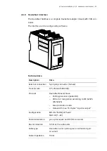
Страница 15: ...uts and outputs a port for the analog weighing electronics ADC a supply voltage connection a RS 485 interface a network port a ProfiBus DP interface The ProfiBus DP connection is established by D Sub...

Страница 16: ...al inputs and outputs a port for the analog weighing electronics ADC a supply voltage connection a RS 485 interface a network port a DeviceNet interface The DeviceNet connection is established by 5 pi...

Страница 17: ...ital inputs and outputs a port for the analog weighing electronics ADC a supply voltage connection a RS 485 interface a network port a CC Link interface The CC Link connection is established by 5 pin...

Страница 18: ...puts and outputs a port for the analog weighing electronics ADC a supply voltage connection a RS 485 interface a network port a ProfiNet I O interface The ProfiNet I O connection is established by RJ...

Страница 19: ...nputs and outputs a port for the analog weighing electronics ADC a supply voltage connection a RS 485 interface a network port an EtherNet IP interface The EtherNet IP connection is established by RJ...

Страница 20: ...l inputs and outputs a port for the analog weighing electronics ADC a supply voltage connection a RS 485 interface a network port an EtherCAT interface The EtherCAT connection is established by RJ 45...

Страница 21: ...pes 21 3 1 9 PR 5215 10 This type includes 3 digital inputs and outputs a port for the analog weighing electronics ADC a supply voltage connection a RS 485 interface a network port an analog output Se...

Страница 22: ...onics ADC a supply voltage connection a RS 485 interface a network port a ProfiBus DP interface an analog output Note The Profibus DP interface and the analog output are located on a so called CombiCa...

Страница 23: ...t connection The device is snapped to a mounting rail The menu guided adjustment and configuration of the device are carried out on a notebook PC via ethernet Adjustment using weights according to the...

Страница 24: ...3 Device description 3 3 Housing 24 For the LAN interface ModBus TCP Ethernet TCP IP OPC 3 3 Housing 3 3 1 Housing dimensions Example PR 5215 00 All dimensions in mm...

Страница 25: ...3 Device description 3 3 Housing 25 3 3 2 Indicator front Pos Name 1 TFT Color touch display 1 77 2 Ethernet port 3 CAL switch...

Страница 26: ...3 Device description 3 3 Housing 26 3 3 3 Overview of connections...

Страница 27: ...og weighing platforms and analog load cells can be connected via a cable junction box 1 analog output The analog output can be used to control valves for example Supply voltage connection UDC 24 V RS...

Страница 28: ...ack Red Blue 24 VDC 9 W POWER SUPPLY DIGITAL OUT RS 485 422 13 14 15 16 PE PE 23 22 21 24 20 19 18 17 DO1 DO2 DO3 DOGND RxB TxB R D RxA TxA The connection diagram is located on the right side of the h...

Страница 29: ...er lines Measurement cables should be laid in separate cable conduits Network cables should be crossed perpendicularly Further procedures Check the consignment make sure that all components are presen...

Страница 30: ...transportation of Minebea Intec devices was designed to avoid transport damage It is recommended that the box and all parts of the packaging should be kept for future storage or transportation of the...

Страница 31: ...m temperature for approx two hours 4 2 6 cable connection Have all required parts technical documents and tools at hand for control cabinet installation Other procedure Install the mounting rail 35 mm...

Страница 32: ...stablish equipotential bonding between devices system components this is essential for Ex applications Use a standardized reference potential Connect the mounting rail to protective ground Keep measur...

Страница 33: ...unauthorized access The current IT security guidelines must be followed so as to minimize the risks 4 3 1 1 Ethernet port The Ethernet port contains a powerful TCP IP interface connection with transfe...

Страница 34: ...ial isolation yes Cable type CAT 5 patch cable twisted pair screened Cable impedance 150 Cable length max 115 m 4 3 2 RS 485 interface The device is equipped with an integrated RS 485 interface The in...

Страница 35: ...otocol none Signals TxA RxA R TxB RxB R Potential isolation yes Cable type Twisted pair screened e g LifYCY 2 2 0 20 1 pair of wires for ground GND Cable gauge 1 5 mm 2 Cable length max 1000 m preset...

Страница 36: ...tage Low UDC 0 5 V High UDC 10 30 V Passive external power supply required Input current 11 mA UDC 24 V 5 mA UDC 12 V Signals DIGND common for all inputs Potential isolation yes via optocoupler Cable...

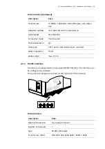
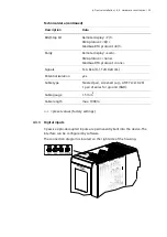
Страница 37: ...can be conigured by software The connection diagram is located on the right side of the housing Technical data Description Data External connection 4 pin plug connector Number of outputs 3 DO1 DO2 DO...

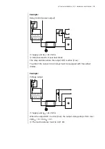
Страница 38: ...or free wheel diode The relay switches when the output DO1 is active true To protect the output circuit relays must be equipped with free wheel diodes Example Voltage output Supply unit UDC 24 V 0 5 A...

Страница 39: ...circuit overload Analog platforms can be connected to the device see Chapter Connecting an analog weighing platform with a 6 wire cable Load cells can be connected to the device as follows One load ce...

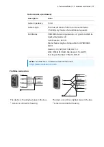
Страница 40: ...nal LC output gray S Sense Sense white S Sense Sense black PE Screen Supply Supply excitation red Supply Supply excitation blue PE Screen Note The colors listed here apply for the Minebea Intec produc...

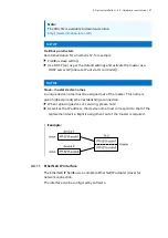
Страница 41: ...4 Device installation 4 3 Hardware construction 41 4 3 5 2 Connecting an analog weighing platform with a 6 wire cable Connection example Screen Mounting rail Potential equalization...

Страница 42: ...n 42 4 3 5 3 Connecting a load cell with a 4 wire cable Connection example Provide the following links between the terminal contacts from Supply V to Sense S from Supply V to Sense S Further connectio...

Страница 43: ...via cable junction box PR 6130 using connection cable PR 6135 or PR 6136 Recommendation Install cable in steel pipe connected to a ground potential The distance between the measuring cables and the p...

Страница 44: ...de Depending on the design of the cable junction box used either the jumper J3 must be removed or the cable screens must be disconnected from the terminal contacts highlighted in yellow Connection exa...

Страница 45: ...th the load cells connected can be carried out with a multime ter Note In the case of an external load cell supply voltage or use of an isolating unit the internal load cell supply is not relevant Sup...

Страница 46: ...4 Device installation 4 3 Hardware construction 46 Measuring voltage 0 5 mV LC with 1 0 mV V 0 10 mV LC with 2 0 mV V Measuring voltage 0 V 0 5 V...

Страница 47: ...n Data External connection 4 pin plug connector Number 1 active current output 0 4 20 mA max 24 mA 10 V output voltage via ex ternal 500 resistor Function Gross Net weight Transparent Selected config...

Страница 48: ...ble type Twisted pair screened e g LifYCY 2 2 0 20 Cable length 150 m screened Analog signal current output 0 4 20 mA 500 Current is supplied directly via the terminal contacts Analog signal voltage o...

Страница 49: ...to IEC 61158 The interface can be configured by software Technical data Description Data External connection D Sub 9 pin plug connector female Transfer rate 9 6 kbit s to 12 Mbit s baud rate auto det...

Страница 50: ...V grants to HMS In dustrial Networks AB Certificate No Z01951 Model Name Anybus CompactCom 40 PROFIBUS DP V1 Revision 1 8 SW FW 1 08 HW 1 0 GSD HMSA1815 GSD File Version 16 8 2019 Test Report Number P...

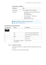
Страница 51: ...Send receive data Data core B D P 4 if required RTS Request To Send only when using a repeater 5 DGND Insulated GND to RS 485 side 6 VP Insulated power supply 5 V to RS 485 side 7 not connected 8 RxD...

Страница 52: ...plug connector female Transfer rate 125 250 and 500 kbit s Protocol DeviceNet Master Slave Polling procedure polled IO CRC error recognition according to IEC 62026 EN 50325 Max 64 station nodes Data w...

Страница 53: ...ute 1 90 Device Type Attribute 2 0x2B Device Profile Name Generic Device keyable Product Code Attribute 3 63 Product Name Attribute 7 CompactCom 40 De viceNet Product Revision Attribute 4 1 006 SOC Fi...

Страница 54: ...iption Data External connection 5 pin plug connector female Transfer rate 156 625 kbps 2 5 5 10 Mbps Protocol CC Link Slave CRC error recognition according to IEC 62026 EN 50325 Max 64 station nodes 1...

Страница 55: ...er 934 Note The CSPP file is available to download online http www minebea intec com Allocation of the 5 pin plug connector Pin assignment Signal Description 1 DA Communication RS 485 RxD TxD 2 DB Com...

Страница 56: ...I O Connection mode Network Configuration XML file GSDML Vx xx Minebea PR5215 2 Port xxxxxx xml Potential isolation yes Cable type Twisted pairs screened e g patch cable CAT5 Autolink straight or cro...

Страница 57: ...controller NOTICE Slave master device names A unique device name must be assigned out of the master This name is given highest priority when establishing a connection When replacing devices or servic...

Страница 58: ...col EtherNet IP Connection mode Network Configuration EDS file min_5215_ethernetip eds Potential isolation yes Cable type Twisted pairs screened e g patch cable CAT5 Au tolink straight or crossover Ca...

Страница 59: ...rates of almost 200 MBit s can be achieved EtherCAT is an open technology that is standardized in IEC 61158 and IEC 61784 as well as in ISO 15745 4 The interface can be configured by software Technic...

Страница 60: ...reened e g patch cable CAT5 Au tolink straight or crossover Cable impedance 150 Cable length to HUB max 115 m Certificate Product Name Anybus CompactCom 40 Ether CAT Product Code 0x36 Revision Number...

Страница 61: ...t date time Set up the network only necessary if the device is to be used or con figured in the network see Chapter Connect device to the network 5 2 Switching off the device The device is switched of...

Страница 62: ...d connected to the network The device is switched on 1 Connect the device to the network via network cable 2 Show the IP address factory setting on the display under View settings Interfaces Network 3...

Страница 63: ...switched on The device uses the last IP or the default IP if it does not receive an IP from a DHCP server Connecting the device is de scribed below Requirements Notebook PC is switched on and connecte...

Страница 64: ...5 Getting started 5 5 Connect device to the network 64 5 Under Networking select the protocol shown and click Properties A window appears...

Страница 65: ...8 Enter the same subnet mask as PR 5215 see display 9 Confirm the selection with OK 10 Open a WEB browser on the notebook PC and enter the IP address in the input field of the WEB browser and confirm...

Страница 66: ...2 If necessary make further settings in consultation with the responsible system administrator 13 Save the settings 5 6 Data backup Additional overwrite protection is provided for adjustment calibrati...

Страница 67: ...gainst unauthorized access The CAL switch is located on the front of the device Write protection not activated Write protection activated opened closed Changes to the metrological parame ters can be c...

Страница 68: ...st name are not affected by this Restarting has the following effects on the device Current process steps are deleted The factory default settings are restored Service 1 Click More functions Backup Re...

Страница 69: ...creen and consists of keys and displays Pos Name 1 Menu button 2 Current date 3 Icon for warning and status displays 4 Current time 5 Key for switching views 6 Weight value 6 digits decimal point 7 We...

Страница 70: ...6 Operating 6 1 Operating and display elements 70 6 1 2 WEB display The display consists of various areas Pos Name 1 Menu selection 2 Header 3 Info line 4 Info pane 5 Taskbar...

Страница 71: ...d display elements 71 6 1 2 1 Menu selection After logging in the website appears with the menu selection hidden By clicking the menu selection is displayed By clicking on the individual menu items th...

Страница 72: ...age Date and time Menu selection Icon Description Display menu selection Hide menu selection Weighing point area metrology View Description Displays the weighing point and metrology information and th...

Страница 73: ...6 1 2 3 Information line The information line shows the user the current menu position during opera tion 6 1 2 4 Info pane The window shows one of the following views at a time Parameter lists Input...

Страница 74: ...6 Operating 6 1 Operating and display elements 74 6 1 3 Message dialog Example If Save was clicked the following dialog appears Click Ok to save finally...

Страница 75: ...gs Viewing the following menus Weighing Measuring time Digital filter Cut off frequency Standstill time Standstill range Tare condition Tare timeout Zeroset range Zerotrack Zerotr indic range Zerotrac...

Страница 76: ...ay Modbus TCP adr Serial Interface Protocol Baud rate Data bits Parity Stop bits Digital I O Input 1 3 Output 1 3 Analog output Mode Range Output on wgt err On 0 On Max Weight value f 0 4 mA Weight va...

Страница 77: ...mask EtherNet IP Use DHCP IP address EtherCAT IP address Subnet mask System Languages Operation language Display language Date Time Date format Date seperator Time format Time seperator Info Battery s...

Страница 78: ...cheff Cut off frequency Input 0 00 40 00 Hz Standstill time Input 0 00 2 s Standstill range Input 0 01 10 00 d Tare condition Selection Tare without standstill Tare after standstill Tare timeout Input...

Страница 79: ...ell Gravity Input Gravity at the place of installation default is the value for Hamburg Germany 9 81379 m s 2 Hysteresis error Selection not specified specified Correction A Only by selection specifie...

Страница 80: ...ell specific Input from the calibration certificate of the load cell under Output impedance 6 3 2 Application settings Limits Limit 1 3 on Input Weight value Limit 1 3 off Input Weight value 6 3 3 Int...

Страница 81: ...d Other interfaces Fieldbus ProfiBus DP Slave address Input 1 126 DeviceNet Slave address Input 1 128 Baud rate Selection 125 k 250 k 500 k DeviceNet MAC ID Input 1 62 CC Link Slave address Input 1 64...

Страница 82: ...y via D11 Range Selection 0 20 mA 4 20 mA Output on wgt err Selection Hold 0 mA 4 mA 20 mA On 0 Selection Linear 0 mA 4 mA 20 mA On Max Selection Linear 0 mA 4 mA 20 mA Analog value Only by selection...

Страница 83: ...mmyyyy mmddyyyy yyyymmdd yyyyddmm d day m month y year Date seperator Selection Slash Hyphen Period Time format Selection 12 h 24 h Time seperator Selection Colon 6 3 5 Service Contact address Input o...

Страница 84: ...evice is booted the following window appears 1 Click OK The input field appears 2 Click the New password input field and enter a password 3 Click the Confirm password input field and enter the passwor...

Страница 85: ...6 Operating 6 4 Assign password 85 5 Enter the previously assigned password under Password 6 Click Login The window ADC parameters appears...

Страница 86: ...6 5 Change password 86 6 5 Change password 1 Click Change password in the header under An input window appears 2 Enter the current password 3 Enter the new password 4 Enter the new password again and...

Страница 87: ...lost it must be unlocked The following steps are necessary to unlock the password 1 Click Forgot Password An information window appears 2 Paste this information into an e mail message and send to hel...

Страница 88: ...rating language line A selection window appears Selection English default Japanese German French Spanish Italian 2 Select the desired operating language 3 Click in the Display language line A selectio...

Страница 89: ...current time 2 Click in the row Date format A selection window opens Selection ddmmyyyy mmddyyyy yyyymmdd yyyyddmm 3 Click in the row Date separator A selection window opens Selection Forward slash d...

Страница 90: ...e Remote display SMA Modbus RTU Baudrate Selection 300 600 1200 4800 9600 19200 Baud Other parameters are protocol specific 3 Save the settings 6 10 Digital inputs outputs Digital inputs outputs 1 Sel...

Страница 91: ...s refer to the gross weight SPM addresses for the limits see Chapter System data Example 1 The output signal Limit 1 out of limit 1 Limit 1 switches OFF above a weight Wgt of 900 kg The output signal...

Страница 92: ...t 1 Limit 1 out switches ON if the weight Wgt exceeds the value output 2 Limit 2 out switches OFF if the weight falls below the value Limits 1 Select the individual parameters and change if necessary...

Страница 93: ...put in D30 Instrument is controlled via PLC Gross Gross weight output in D8 Net Net weight output in D9 only if tared other wise gross weight is output Mode Select Gross net value output on the displa...

Страница 94: ...ined This is only possible if the out put value for Max is 20 mA 0 mA In the event of a weight Max the output is set to 0 mA 4 mA In the event of a weight Max the output is set to 4 mA On Max 20 mA In...

Страница 95: ...time Measuring time The duration of a measurement can be selected Selection 10 ms 20 ms 40 ms 80 ms 160 ms 320 ms 640 ms Digital filter Note After changing the filter parameters a new adjustment may b...

Страница 96: ...ded Measuring time 160 ms Digital filter Aperiodisch Cut off frequency 2 00 Hz Cut off frequency The smaller the cutoff frequency the slower the measurement and the more stable the measurement result...

Страница 97: ...set range Define a range around the zero point determined by the dead load dur ing adjustment within this range the displayed gross weight can be set to zero by a corresponding ex ternal command and a...

Страница 98: ...eighing point 6 14 1 General instructions The transmitters of the PR 5215 series do not have legal for trade approval The legal for trade application of PR 5215 with other devices has to be verified T...

Страница 99: ...ity Max 3 Determining the scale interval Scale interval see Chapter Determining the scale interval 4 Determining the dead load Dead load see Chapter Determining the dead load 5 Adjustment with weight...

Страница 100: ...1 Under Max capacity enter max capacity with decimal places in this example 6000 and select the mass unit in this example g 2 Click Set max capacity in the task bar to save the entries 6 14 2 2 Determ...

Страница 101: ...nt mV V dead load load cell sensitivity Cn mV V load cell capacity maximum capacity Emax number of load cells load cell sensitivity Cn rated output Cn see technical data for the load cell Normally cal...

Страница 102: ...t the place of installation can be taken into account The PR load cell data is based on the acceleration of gravity in Hamburg Germany 9 81379 m s 2 Calculating Span Span indicates the equivalent inpu...

Страница 103: ...of loadcell Maximum capacity Emax of a load cell not the total maximum capacity of the scale Input For the value refer to the technical data of the load cell Gravity Gravity at place of installation D...

Страница 104: ...h selection All load cells the same Input refer to the load cell certificate under Output impedance LC 1 to 8 Output at max capacity Only with selection Each load cell individual Input refer to the lo...

Страница 105: ...nt see Chapter CAL switch 6 14 3 1 Subsequent dead load correction If the vessel platform weight changes by an amount that is higher than the zero range e g due to dead load reduction dead load increa...

Страница 106: ...d simple and reliable communication between a PC or PLC and up to a maximum of 127 devices The ModBus protocol allows access to all data published in the SPM table of the relevant application Implemen...

Страница 107: ...ed as an interface Fixed interface settings are 8 bits no parity and 1 stop bit The commands to the transmitter are printable ASCII characters starting with LF 0A hex and ending with CR 0D hex The tra...

Страница 108: ...if there are no changes to the data content Concept definition Term Abbreviation Description Master Field bus master usually an SPS Slave Field bus device MOSI Master Out Slave In data is written fro...

Страница 109: ...he function for writing data 6 free free free free free free free free 7 Get Fix Tare Set Fix Tare Res Pow er Res Test Set Test Res Tare Set Tare Set Zero In direct access control bits are independent...

Страница 110: ...ains the data to be written e g gross value 4 Read_Value_Selected Read_Value_Select func tion from the write win dow is mirrored if the data in Read data is available 5 Write Active Power Fail Out put...

Страница 111: ...taring CmdError 1 bit The device has interrupted the execution of a command e g standstill could not be reached within the defined standstill time The error number can be read from LASTER ROR see Cha...

Страница 112: ...or see Chapter Function number 1 scale status read 9 2 2 Reading and writing data with function numbers 9 2 2 1 Reading data Procedure 1 Write the function number as Read_Value_Select in byte 4 of the...

Страница 113: ...e reaction Write value in Write_Data bytes 0 3 Write function number to Write_Value_S elect Read data from Write_Data bytes 0 3 Set the Write_Active bit Wait until Write_Active has been set Write 0 in...

Страница 114: ...read window is only possible with a corresponding function number and the data in Read_ Data Byte 0 3 of the read window In those bytes the bits must be evaluat ed individually The procedure is the s...

Страница 115: ...n When an action requiring more time is started the end of execution can also be waited for Action of the master Slave reaction For setting bits see Chapter Writ ing bits or Writing control bits Set t...

Страница 116: ...ead Function number 5 device type and software version read see Chapter Function number 5 device type and software version read Function number 6 serial number of the weighing point read see Chap ter...

Страница 117: ...2 Limit 3 Limit 2 Limit 1 Byte 3 9 2 5 2 Function number 1 scale status read Dynamic status Bit 7 Bit 6 Bit 5 Bit 4 Bit 3 Bit 2 Bit 1 Bit 0 Byte 0 OutOf Range Standstill Inside ZSR Center Zero Below...

Страница 118: ...f 36 mV Cannot read weight values from ADC ana log digital converter ERR 9 E7 The measuring signal is negative inverse conversion ERR 7 E6 Sense voltage not present or too low ERR 6 E3 The measuring s...

Страница 119: ...rs EXPO UNIT STEP must be read again Set after Power on and reset after reading Max FSD Full scale deflection Tare_Active The scale has been tared 9 2 5 3 Function number 2 For internal use only 9 2 5...

Страница 120: ...255 1 g grams 2 kg kilograms 3 t tons 4 lb pounds 2 STEP One byte for the scale interval content in decimal form 0 to 255 1 scale interval 1 2 scale interval 2 5 scale interval 5 10 scale interval 10...

Страница 121: ...SB Byte 1 TYPE LSB Byte 2 MAINVERSION Byte 3 SUBVERSION e g PR 5215 Rel 1 23 52150123hex 9 2 5 7 Function number 6 serial number of the weighing point read Bit 7 Bit 6 Bit 5 Bit 4 Bit 3 Bit 2 Bit 1 Bi...

Страница 122: ...ise 0 Function number 11 Current gross net weight selected with bit 72 Function number 14 max capacity Max 9 2 5 10 Function number 24 29 Limit value Read Write Function number 24 Limit 1 on Function...

Страница 123: ...riting bits The bit is reset at the specified number 128 Function number 80 SetZero Set the gross weight to zero Function number 81 SetTare The weighing point is tared Function number 82 ResetTare Res...

Страница 124: ...see Chapter Writing bits Function number 112 SetZero Function number 113 SetTare Function number 114 ResetTare Function number 115 SetTest Function number 116 ResetTest Function number 117 ResetPwf Fu...

Страница 125: ...9 2 Scale protocol 125 9 2 6 Example reading the gross weight Input range MOSI Byte Value Description 0 1 2 3 4 08 Read the gross weight for function number 8 see Chapter Function num ber 8 11 14 wei...

Страница 126: ...ected 5 Write Ac tive Pow er Fail 6 Cmd Busy Cmd Error Tare Ac tive Cal Chan ged Test Ac tive 7 Out Of range Stand still In side ZSR Cen ter Zero Be low Zero Over load Above Max ADC Error In direct ac...

Страница 127: ...problem does not arise due to compensation by the firmware Sequence of data bytes 0 3 Standard sequence Sequence for Device Net and EtherNet IP Byte 0 Read data 0 MSB Byte 0 Read data 3 LSB Byte 1 Rea...

Страница 128: ...een digital inputs and outputs and the SPM via the I O configuration Note If a text is defined e g from SPM address B401 this must be defined in the OPC server from SPM address B400 so that the conten...

Страница 129: ...ATE and TIME_OF_DAY STRING variable long charac ter string max 255 characters ISO WSTRING variable long wide character string max 255 characters Uni code BYTE bit sequence 8 WORD bit sequence 16 DWORD...

Страница 130: ...the zeroset range ZSR The weight is stable Weight Zero or Max max capacity FSD Full Scale Deflection B5 X40 X41 X42 X43 BYTE BOOL BOOL BOOL BOOL R R R R R ADC status Measuring signal negative Error 7...

Страница 131: ...error B19 0 B16 SINT R Exponent Number of decimal places Example 1 23 is displayed Exponent 2 B17 SINT R Weight unit 1 g 2 kg 3 t 4 lb B18 SINT R Verification scale interval for multi interval multi...

Страница 132: ...max capacity FSD Full Scale Deflection D23 DINT W Activity counter test of communication with device D24 DINT W Limit 1 on D25 DINT W Limit 1 off D26 DINT W Limit 2 on D27 DINT W Limit 2 off D28 DINT...

Страница 133: ...permissible range of 36 mV Measuring cable is interrupted cable break detection Other hardware defect ERR 6 No sense voltage Load cells not connected Sense line or supply line is interrupted Wrong po...

Страница 134: ...weights 7 cal active Adjustment is active no weights 8 no standstill No standstill of the scale 13 tare is active Tare is active 16 weight has error Weight error 18 cannot tare below zero Taring below...

Страница 135: ...orized specialists to ensure trouble free and safe operation of the device and to ensure that the warranty remains valid WARNING Improper repairs can pose considerable risks to the user Immediately di...

Страница 136: ...caused by unsuitable cleaning utensils products Damage to the device Prevent moisture from penetrating the interior Do not use aggressive cleaning agents solvents or similar agents For use in the food...

Страница 137: ...e connection cable if the weighing platform weighing facility and weighing indicator no longer work after prolonged storage under unfavorable conditions after heavy transport stresses Immediately disc...

Страница 138: ...old products any single use or rechargeable batteries should be removed and taken to a suitable collection point The type of battery used is specified in the technical data Please see our General Ter...

Страница 139: ...buffer The lithium battery as a buffer for the date time chip and as a buffer for the supply voltage so the device can be switched on again Device continuously connected to mains voltage up to 10 yea...

Страница 140: ...strong vibrations 15 3 2 Electromagnetic Compatibility EMC All data in compliance with EN 61326 industrial section High frequency electromagnetic fields 80 1000 MHz EN 61000 4 3 10 V m High frequency...

Страница 141: ...ncy coupling 0 15 80 MHz EN 61000 4 6 3 V 15 3 3 RF interference suppression Electromagnetic emission pursuant to EN 61326 Limit class A for industrial areas 15 4 Weighing electronics data 15 4 1 Load...

Страница 142: ...th Tschebyscheff Cut off frequency adjustable 15 4 3 Accuracy and stability Accuracy 6 000 d acc to OIML R76 Klasse III Min measuring signal 6 000 d 0 6 mV V 5 V supply 0 5 V d Linearity 0 01 Zero poi...

Страница 143: ...tion box and device PR 6135 PR 6135A max 500 m length of the load cell cable 15 5 Mechanics 15 5 1 Housing Material Polyamide Surface finish Untreated Color RAL Light gray 7035 UL 94 flammability clas...

Страница 144: ...16 Appendix 144 16 Appendix 16 1 Certificates Ser no Name Document no 1 EU Declaration of Conformity MEU22001...

Страница 145: ...16 Appendix 16 1 Certificates 145 1 5...

Страница 146: ...s overensstemmelse med Deutsch de E el espa ol es Konformit tserkl rung Declaraci n de conformidad 1 Produktmodell Produktnummer gilt ausschlie lich f r Projekt Nr 2 Name und Anschrift des Herstellers...

Страница 147: ...ije u vezi s kojima se izjavljuje sukladnost magyar hu italiano it Latvi kalba lt Megfelel s gi nyilatkozat Dichiarazione di conformit Atitikties deklaracija 1 Term kmodell term ksz m kiz r lag az al...

Страница 148: ...oegepaste relevante geharmoniseerde normen of van de overige technische specificaties waarop de conformiteitsverklaring betrekking heeft polski pl portugu s pt rom n ro Deklaracja zgodno ci Declara o...

Страница 149: ...licevanja na druge tehni ne specifikacije v zvezi s skladnostjo ki je navedena v izjavi 1 Tuotemalli tuotenumero koskee vain projektinumeroa 2 Valmistajan 2 1 ja valtuutetun edustajan 2 2 nimi ja osoi...

Страница 150: ...Published by Minebea Intec GmbH Meiendorfer Strasse 205 A 22145 Hamburg Germany Phone 49 40 67960 303 Email info minebea intec com www minebea intec com...

Отзывы: