43
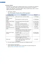
(2) Cable of connecting RS-485 Converter and Drive Module
Connector Type : RJ45
Cable Type : LANcable, CAT5 or better (UTP or STP)
Signal Wiring : Standard Straight Wiring ( 1<->1, 2<->2, 3<->3,…, 8<->8 )
If multi-axis connection is required at one segment, up to 16 drive modules can be
connected by the daisy-chain method. The pin signal content is as follows.
RJ45 Pin No.
UTP CAT5 cable
Function
1
White/Orange
GND
2
Orange
GND
3
White/Green
Data+
4
Blue
GND
5
White/Blue
GND
6
Green
Data-
7
White/Brown
GND
8
Brown
GND
case
Frame GND
"The chassis of connector is connected with the Frame GND through
a mount hall of the PCB. In this case, use the STP CAT5E cable
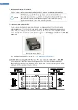
7-2. Communication Interface Circuit
It shows the input / output circuit of RS-485 communication interface signal. When the
product is installed at the end of the network configuration, connect the terminating resistor to
the data pin as shown in the figure. MECQ2 keeps receiving mode usually and transmits only
while responding to the receiving command.
For more information of communication function, refer to
「
CK10_UserManual_Communication Function_MODBUS
」
in a separate volume.
The cable length of RS-485 Converter<->Drive or Drive<->Drive
must be longer than 60 cm.
Signal cable ‘Data+’ and ‘Data-’ are differential type signals. These
two signal cables must be twisted.
Caution
Caution
Caution
Terminal
Resistance

