background image

Chapter 6 Basic usage

6-53

2

2

2

6

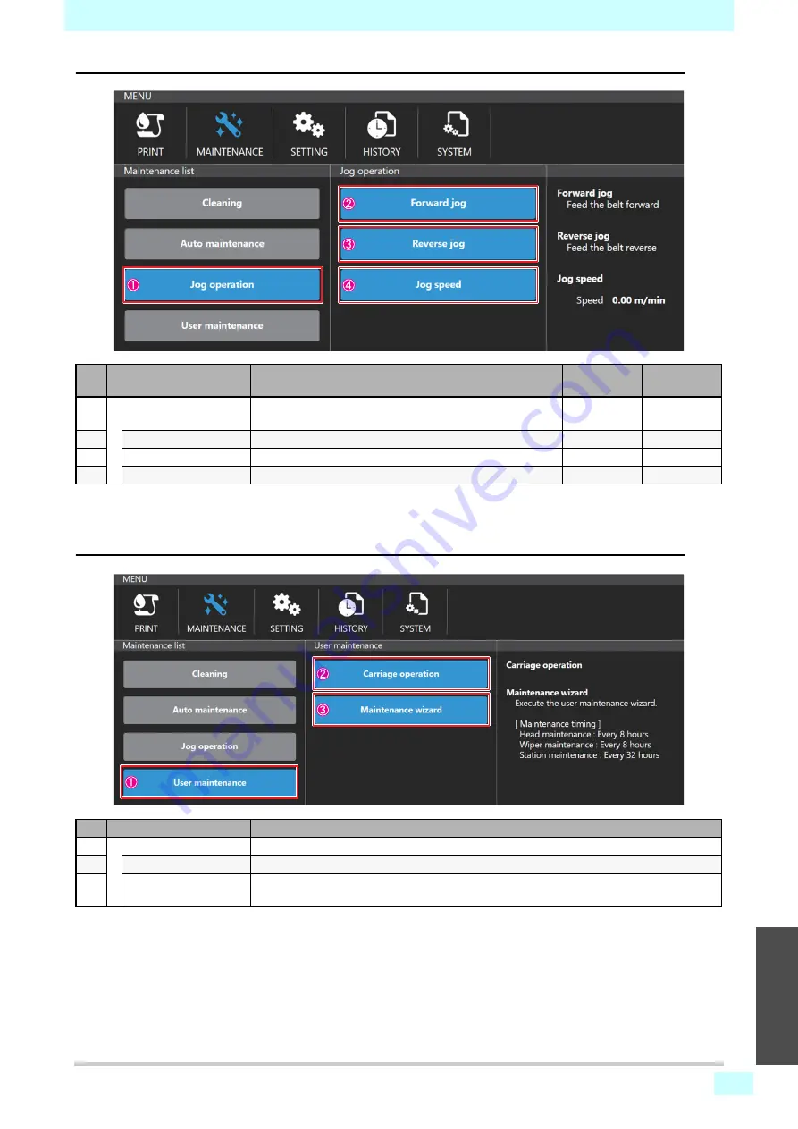
[Jog operation]

[User maintenance]

No.

Name

Description

Initial value:

Recommended

value:

1

Jog operation

The [Forward jog], [Reverse jog], [Jog speed] menu will 
be displayed.

2

Forward jog

Operate Forward jog with [Start], [Stop] buttons.

3

Reverse jog

Operate Reverse jog with [Start], [Stop] buttons.

4

Jog speed

Set the feed speed (0.01 to 5.00 m / min).

2.0

2.0

No.

Name

Description

1

User maintenance

The [Carriage operation] and [Maintenance wizard] menus are displayed.

2

Carriage operation

Move the carriage to [Maintenance position] or [Parking position].

3

Maintenance wizard

Follow the instructions on the screen to perform head maintenance, wiper maintenance, 
and station maintenance.

Содержание ML Tiger-1800B MKII

Страница 1: ...MIMAKI ENGINEERING CO LTD https mimaki com COLOR INKJET PRINTER ML Tiger 1800B MK III D203491 11 Original instructions ...

Страница 2: ...written consent The use which does not obtain consent from our company is considered to be an unintended use In this case we assume no responsibility for property damage or personal injury and regard the warranty of this machine as invalid Misuse of this machine can cause it to stop working for a long time If this happens our engineer must deal with it in order to restart the operation Images in t...

Страница 3: ...ii 1 2 2 4 5 6 ...

Страница 4: ...er 3 Usage Precautions The Intended Use 3 2 Unauthorized Use 3 2 Emergency Stop by Operator 3 2 The Service Life of This Machine 3 2 Chapter 4 Installation Outline 4 2 Aptitude of Workers 4 2 Preparing the Installation Site 4 2 Installation Requirement 4 3 Loading Placement Installation procedure 4 3 Lifting Procedure 4 4 Unpacking and Placement 4 5 Connection 4 7 Storage Condition 4 8 Chapter 5 P...

Страница 5: ...to Workers Operators 7 2 Operators 7 2 Operator Work 7 2 Preparation Before Starting Work 7 2 Transport of media 7 3 Printer 7 4 Pause 7 4 Long term Suspension 7 4 Procedure for Cleaning and Adhesive Application 7 5 Preparation of Belt Cleaning Unit 7 5 Adjust the Squeegee Blade 7 6 Replacing Squeegee Blade 7 7 Belt Cleaning Procedure 7 10 Cleaning 7 10 Change Wiper Blade 7 11 Replacing Ink Tank 7...

Страница 6: ...v Troubleshooting 9 5 Dismantling 9 27 ...

Страница 7: ... Purpose of Operation Manual 1 2 Documents Supplied with This Machine 1 2 Manufacturer s Authorization 1 2 Normative Standard 1 2 Handling of This Manual 1 3 Safety Precaution 1 5 Electrical Equipment 1 7 General Safety Instructions 1 7 Warning Label 1 9 Warning Label Display Position 1 12 Chapter 1 Introduction ...

Страница 8: ...ctrical drawings Explain the main system of this machine It is intended for engineers who solve problems Maintenance parts list It is not included Manufacturer s Authorization Mimaki has been approved as a machine maker according to the legislation through the following certificates Operation manual this manual CE Declaration of Conformity Normative Standard Revisions of this machine and manuscrip...

Страница 9: ...e procedure S Mode Key Indication Operation Reference 1 Manual operation 2 P01 No 3 Emergency reset Luminous pushbutton press it to reset the machine work returning the machine to the initial phase 5 3 3 AUT Automatic operation 4 Confirm whether it is executed correctly End of procedure Meaning Danger Failure to observe the instructions given with this symbol can result in death or serious injurie...

Страница 10: ...pair use spare parts other than original Note It is strictly forbidden to the customer and or third parties except authorized employees of Mimaki to make changes of any kind and size on the machine and its functions and to this manual Table Column data S Step It identifies the step Mode There are the following modes Manual Require to press a pushbutton or a function key Use visual control operatio...

Страница 11: ...peed turn OFF the belt heater Places where there is a possibility of contact with the Primary power supply should not be opened in the power ON state electrical unit of main unit carriage rear cover and electric unit in heater electric unit When working on at the lower surface of the carriage in the maintenance space make sure to open the door after the carriage reaches the maintenance space ...

Страница 12: ...6 Be careful not to get your hands caught in the cleaning unit Be careful not to pinch your hands on the tension bar Be careful not to pinch your hands on the pressure roller Be careful not to get your hands caught in the cover ...

Страница 13: ...eir qualifications and the intervention procedures are optimized to ensure safety and health of them and achievement of their final objective If the work contents and work procedures are changed and the number of operators is increased or decreased there is a possibility that the safety of the operators themselves may be exposed to serious danger or the desired results may not be obtained Be caref...

Страница 14: ...ing Before doing anything work on all preventive measures and take them Do not leave the machine unattended when in use Make sure that the entire work area is clearly visible Always keep the work area clean If there is any abnormality in the operation of the on board equipment notify our maintenance person Avoid loose clothing and wear protective clothing Safety during maintenance Maintenance oper...

Страница 15: ... Fig Caution label movable part M903330 Caution label works M912054 Caution label pinching M907935 Label Danger voltage M910931 Caution label front cover falling M901581 Caution label M909381 Caution label Y bar M903764 Caution label UV power voltage M914168 Caution label applying glue ...

Страница 16: ...aution label movable part M903239 Caution label Temperature Part No Label name Fig Prohibition label prohibition on removal of safety guard M903406 Ground label M913888 Label C 10 mark M916752 Tiger1800B Mk3 rated label M915604 Caution label two outlet M915603 Power connection label ...

Страница 17: ...Chapter 1 Introduction 1 11 1 2 3 4 5 6 M915602 Feeding relay connector rated label M915605 X12ETH 3 Mark label M915601 PC outlet rated label M915598 DRYERJET rated label M915608 Main switch label ...

Страница 18: ...emove the warning label on the machine Make sure that the label is clearly legible and not covered with parts If the label deteriorates contact us and change it 1 Electrical box M907935_Label Danger voltage M903406 00_Ground label M903764_Caution label UV power voltage ...

Страница 19: ...elt Front Rear 3 Carriage Caution label applying glue Caution label belt M901581_Caution label Caution label belt M901581_Caution label M912054_Caution label pinching M907935_Label Danger voltage M909381_Caution label Y bar M903406_Ground label ...

Страница 20: ...ntroduction 1 14 4 Left front cover 5 Left rear cover 6 Right rear cover M903330_Caution label works M907935_Label Danger voltage M903330_Caution label works M903330_Caution label works M903330_Caution label works ...

Страница 21: ...Chapter 1 Introduction 1 15 1 2 3 4 5 6 7 Right side cover 8 Station 9 Model label M903330_Caution label works M903330_Caution label works M913888_Label C 10 mark 5mm ...

Страница 22: ...Chapter 1 Introduction 1 16 10 Plastic cover Front M910931_Caution label front cover falling 4 pieces 3 2 1 4 3 2 1 4 ...

Страница 23: ...Chapter 1 Introduction 1 17 1 2 3 4 5 6 Rear M910931_Caution label front cover falling 4 pieces 3 2 1 4 3 2 1 4 ...

Страница 24: ... 1 18 11 Display label Electrical Box side M916752 Tiger1800B Mk3 rated label M915604 Caution label two outlet M915605 X12ETH 3_Mark label 2 1 2 1 1 M915602 Feeding Relay connector rated label M915603 Power connection label ...

Страница 25: ...Chapter 1 Introduction 1 19 1 2 3 4 5 6 M915601 PC outlet rated label ...

Страница 26: ...Chapter 1 Introduction 1 20 ...

Страница 27: ...ain unit for this machine and describes its features Outline Explanation 2 2 Description of Machine Units 2 2 Feeding Unit 2 2 Main Parts of Machine 2 5 Overall Dimensions 2 10 Identification of This Machine 2 11 Chapter 2 Outline Explanation ...

Страница 28: ... blades Applying adhesive to the belt Unload the printed roll The machine consists of the following units Main unit Main belt Pressure roller Heater Belt cleaning unit Ink feeding unit Option Take up unit Feeding unit Description of Machine Units The main units will be explained below Feeding Unit The feeding unit is arranged on the back side of the main unit This unit is directly connected to the...

Страница 29: ... the paper tube of the dough roll 3 Return the air shaft that set the roll to the safety chuck If necessary use a roll lifter Figure below 4 Return the safety chuck to the original position so that the air shaft does not come off during operation Left figure below 5 The metallic protective part shown in the figure is returned to the rest position by the spring inside Right figure below Pneumatic c...

Страница 30: ...ompleted stop the machine and push the check valve the compressed air will come out of the air shaft 11 Release the pressure from the pneumatic brake and vertically placing the safety chuck in manual mode opens the shaft lock 12 Push the top of the shaft lock outward the protected part shown in the following figure moves this protection Figure below 13 Take out the air shaft along with the empty p...

Страница 31: ...n and a rubber belt On the surface of the belt there is a bedding layer that makes the media that passes under the printhead completely adhere and stabilize The belt moves not continuously but intermittently When the belt stops it prints the set image by repeating printing after 1 pass or several passes printing Shaking unit with centering Big roll unit Small roll unit with centering Main belt ...

Страница 32: ...inkles that may affect the final printed media Furthermore it removes air bubbles between the belt and the media The pressure roller descends during printing and contacts the media and transports it The operation of the pressure roller up and down works with a pneumatic piston Heater There are two infrared heaters under the belt and warm the surface of the belt to restore the adhesion of the adhes...

Страница 33: ... under the brush When the belt operation turns off the tank position lowers Three pneumatic pistons at the bottom of the tank ascend during operation and the squeegee blade and brush come into contact with the belt and perform the cleaning operation Washing water is discharged from the valve When maintaining or replacing the brush and squeegee blade you can slide out the tank and pull it out The t...

Страница 34: ...are in contact 3 AUT After the tank rises the squeegee blade moves horizontally in the opposite direction of the belt After the movement the belt feed starts 4 After cleaning the belt the belt stops the pneumatic piston lowers the tank position and the tank leaves the belt 5 AUT The horizontally moving air cylinder sets the squeegee blade of the second tank to the initial position End of procedure...

Страница 35: ...9 2 2 2 5 6 Ink feeding unit Supply genuine ink to the print head attached to the carriage Ink is contained in eight tanks in the cabinet on the right side of this machine Layout of the ink tanks Rear Front 2M 4K 6Bl 8Or 1Y 3C 5Lk 7R ...

Страница 36: ... Outline explanation Overall Dimensions Dimensions of this machine Below is the maximum dimension standard model of this machine Table Feature Data Maximum length 2800 mm Maximum width 5670 mm Maximum height 2030 mm ...

Страница 37: ...h the rated label attached Manufacturer name Mimaki Model ML Type Tiger 1800B MKIII It is prohibited to remove the nameplate and replace it with another nameplate of the same type If the nameplate accidentally breaks or comes off from the machine you are obliged to notify Mimaki and request a replacement label ...

Страница 38: ...2 12 Chapter 2 Outline explanation ...

Страница 39: ...r describes the intended use unauthorized use and the like of this machine The Intended Use 3 2 Unauthorized Use 3 2 Emergency Stop by Operator 3 2 The Service Life of This Machine 3 2 Chapter 3 Usage Precautions ...

Страница 40: ... that case customers will have to call Mimaki official technical staff Emergency Stop by Operator In the event of mechanical failure it is necessary to cut electric hydraulic and pneumatic if any power from the main power supply discharge residual pressure in the circuit and shut down the machine in order to replace damaged parts The Service Life of This Machine The estimated service life of this ...

Страница 41: ...achine Aptitude of Workers 4 2 Preparing the Installation Site 4 2 Installation Requirement 4 3 Loading Placement Installation procedure 4 3 Lifting Procedure 4 4 Unpacking and Placement 4 5 Connection 4 7 Storage Condition 4 8 Chapter 4 Installation ...

Страница 42: ...tile printing model For the sublimation model 4400 or more It is necessary to identify all the places handling the machine in advance from the place secured for transportation to the installation place and to check in advance whether there is a danger zone Pay attention to high pressure or high temperature electrical system liquid or gas conduit It is manda tory to insulate these conduits accordin...

Страница 43: ... occurs it is necessary to accurately check whether there are malfunction or abnormal wear of movable parts Loading Placement Installation procedure When arranging and installing this machine specific work such as lowering the removed parts and placement work etc can be done by the customer As for other work assembly of the machine and connection to the power supply as stipulated in the contract a...

Страница 44: ...operational unit When lifting parts of this machine please check the following figures To lift the assembled wire you can loosen the screw fixing the two rollers and then lift it You can hoist the printer by using the appropriate lifting cable and hooking the cable to the hook shown in the figure below The position of the hook is held by a special metal tie rod yellow When installing check whether...

Страница 45: ... of the machine sufficiently after installing all parts Procedure Unpacking and placement S Mode Key Indication Step Referen ce 1 Open the box 2 Remove the protective stuffing wood and fixture and remove it so as not to damage the machine 3 Do not press the printer from a brushless motor or the like 4 Place the printer in the desired location 5 Remove the contained washing tank 6 Connect air syste...

Страница 46: ... following points There is no indentation or breakage in the protective guard If there is no indentation or damage remove the part and check that the protected part is not damaged All units of this machine are not damaged There is no trace of rust on the unpainted parts There are no traces of crushing or breakage in all external wiring between the electrical box and various maintenance parts motor...

Страница 47: ...oes not obstruct traffic of people and vehicles Provide a refill tube with two valves 1 2 inch recommended diameter This tube stops the air supply of this machine and discharges it during maintenance work The specifications of the compressor are as follows Qualified and authorized personnel means an employee who has experienced special courses and training has experience of installation trial oper...

Страница 48: ... to ensure the safety of people and equipment it is necessary to observe the following rules Make sure the power supply characteristics are compatible with the technical characteristics of the equipment Connect the power and connecting cables firmly and correctly to the corresponding terminals on the machine Connect the shield of the cable to the grounding system above Storage Condition Parts pin ...

Страница 49: ...n a place with the following characteristics Indoor with 7000 x 4000 mm Height 4000 mm At the storage location sufficient mobility and controllability must be ensured so that official approval workers can safely do lifting of equipment safely It is absolutely prohibited to put any substance on the machine ...

Страница 50: ...4 10 Chapter 4 Installation ...

Страница 51: ...This chapter describes the push button panel Work Station 5 2 Push button panel P01 5 3 Push Button Panel P02 5 4 Emergency switch PEM 5 4 Chapter 5 Push Button Panel ...

Страница 52: ...rea of the main power switch turn on and off the voltage to each part of the electric panel To activate the device turn the position of the knob to I corresponding to voltage application If you need to open the cabinet door set the knob position to 0 You can lock the knob so that someone who does not own the key can not use the machine The use of this machine with the guard removed is the responsi...

Страница 53: ...machine and turn off the auxiliary circuit 3 RESET EMERGENCY Emergency reset switch When this button is lit the cycle is stopped After eliminating the cause of the emergency stop release the emergency switch and press the reset button to reset the emergency stop signal 4 EXCLUSION SAFETY DOOR Safety door switch Used to release the limit switch which opens the door of the printer By turning off the...

Страница 54: ...ol lever When tilted upward adjustment of the pneumatic brake applying tension to the media to be extended becomes effective If you lower it this adjustment function will be invalid 2 EMERGENCY Emergency switch With this button you can immediately stop the machine and turn off the power of the auxiliary circuit 3 PRESSURE ROLLERS Pressure roller button When this button is pushed the tension roller...

Страница 55: ...lay 6 21 Alarm icon 6 22 Error description 6 22 Operation restrictions when an alarm occurs 6 23 Idling status 6 23 Printing status 6 23 How to clear the alarm 6 24 Cleaning 6 25 Cleaning at any time 6 25 Auto maintenance setting 6 27 Recommended settings 6 27 Auto maintenance setting screen display 6 27 Auto maintenance setting 6 28 Nozzle recovery 6 30 Nozzle recovery flow 6 30 Creating nozzle r...

Страница 56: ... touch panel Description of screen configuration No Name Description 1 Status bar Shows printer status 2 MENU Menus organized by function group 3 Quick menu Execute the frequently used functions directly from this screen 4 Content Displays the operation screen and information according to the menu 1 Status bar 2 MENU 3 Quick menu 4 Content ...

Страница 57: ...emaining for each ink lot in graph and percentage When the ink level is low an icon is displayed at the bottom right of each ink Type of icon indicating the remaining ink level Ink near end remaining ink 21 to 25 Ink end remaining ink 0 to 20 Ex Display at ink end 3 SYSTEM ALARM The icon is displayed when an alarm is activated The details of alarms are described on SYSTEM ALARM P 6 21 Type of alar...

Страница 58: ...ach maintenance is performed in the wizard format Cleaning Head maintenance Wiper replacement Cleaning unit maintenance etc 3 SETTING Printer setup menu Make various printer settings Print quality setting Printer mechanical setting Automatic function setting etc 4 HISTORY Shows the system history Print history Each maintenance history Alarm history Controller history 5 SYSTEM Displays the system i...

Страница 59: ... refer to the above table and replace touch panel operations with mouse operations No Controller When to use Touch panel Mouse 1 Select Select a job to print Select a menu Select setting or operation items etc Operation Tap Operation Left click 2 Press and hold Select a job to import Select a job to delete Operation Press and hold Operation Right click 3 List scroll Scroll a job list Scroll histor...

Страница 60: ...each item No Control name When to use 1 ON OFF Switch When selecting ON OFF 2 Radio button When selecting one of multiple options 3 Input number When entering number 4 Input number Numeric keypad When entering number 5 Software Keyboard When entering alphabets and symbols ON setting OFF setting ...

Страница 61: ...ogress is displayed when executing long processing Processing screen A message is displayed when processing fails or when processing is not possible Execute processing again according to the message content While the processing screen is displayed other operations are not accepted to prevent misoperation 1 Process execution 2 Processing screen 3 1 Process completion Clear the processing screen 3 2...

Страница 62: ...int status progress Pause restart or cancel during printing Pause Restart Cancel 2 Job management tab Manages jobs JOB LIST Print job selection job import deletion JOB QUEUE List of jobs waiting to be printed JOB HISTORY Printed job history Jobs can be reprinted from the history TEST PATTERN Built in test pattern including adjustment pattern 3 Job list area Displays a list of jobs for each job man...

Страница 63: ...s Perform cleaning if necessary Make sure that the pressure roller is descending and pressing the media Check the ink level and media level Check whether an alarm has occurred If an alarm has occurred remove the cause of the alarm and clear the alarm 1 Import of a job P 6 10 2 Selection of a job to print P 6 14 3 Setting of print conditions P 6 15 4 Start of printing P 6 17 5 Print end and print o...

Страница 64: ...ble disk USB memory into the internal PC Insert the removable disc containing the job into the USB port of the internal PC 2 Tap the JOB IMPORT button After selecting a job tap the JOB IMPORT button to display the Import dialog You can directly select a job on a removable disk but it is recommended that you perform an import before printing as printing may be delayed Delay There is a delay in data...

Страница 65: ...d the job to select 4 Right screen Specify the import destination Move to the folder where you want to copy the job Click ADD NEW FOLDER to pop up Create folder dialog Enter the folder name on the screen and tap the Enter key to create a folder with the entered name and close the Create folder dialog ADD NEW FOLDER button Specifying the import destination ...

Страница 66: ...ed from the removable disk to the specified path The transfer speed depends on the size of the job to be transferred and the performance of the removable disk If the folder name is not entered a folder named NewFolder is created If a folder with the same name already exists the Create folder dialog will be closed without creating a new folder Create folder dialog Copied job ...

Страница 67: ...erate from other Windows PC Use the network search function to search for the computer name TIGERMK2 from the import source PC RIP PC etc or search for the shared folder by specifying the IP address of this machine 2 Import the job to the shared folder Copy the job to the TIGERMK2 shared folder SharedJob The copied job can be printed from the SharedJob folder in the PRINT menu JOB LIST tab Dependi...

Страница 68: ... list area to display the Print condition selection dialog If a job displayed in the JOB LIST tab or JOB HISTORY tab is deleted from the PC the dialog will be displayed but an error will occur when you execute printing Display the Print condition selection dialog Tap a job from the job list area ...

Страница 69: ...Chapter 6 Basic usage 6 15 2 2 2 6 3 Setting of print conditions Enter a condition in the Print condition selection dialog to start printing Print condition selection dialog 1 2 3 8 4 5 6 7 10 9 ...

Страница 70: ...ilable depends on the job s resolution Ex When the value is 1200 dpi it can be used with two or more passes 5 Layer Specify the layer number of layers 1 4 layer 6 Print direction Direction of scanning to be printed is specified Uni direction bi direction 7 Scan speed Specify the scan speed High speed fast standard standard speed High speed cannot be selected for big dot job data If you set the hig...

Страница 71: ...tton to start printing When printing starts the Print condition selection dialog box is closed and the job information and progress being printed are displayed in the JOB STATUS area Print button Prepare for printing Displays the progress of preparation for printing Printing Displaying the progress of printing ...

Страница 72: ...pause is completed Completed When the pause process is performed the carriage returns to the station When the carriage returns to the station the process is completed If the Pause button is tapped in the bi direction print mode printing is performed for the return path and then stopped Depending on the timing of tapping the Pause button it will stop after one round trip printing Print operation bu...

Страница 73: ...eld The processing screen is displayed until the cancellation is completed Completed After canceling the carriage returns to the station When the carriage returns to the station the process is completed After canceling if there are waiting jobs in the JOB QUEUE the information of the next job is displayed in the JOB STATUS field Tap the Restart button to print the next job Print cancel dialog ...

Страница 74: ...d at any time during printing Perform cleaning from the QUICK MENU or MAINTENANCE MENU Refer to Cleaning at any time P 6 25 for cleaning After the pause the carriage returns to the station and cleaning is performed After the cleaning is completed printing resumes automatically ...

Страница 75: ...L button when an alarm occurs the detailed information and the CLEAR ALARM button will be displayed and you can clear the alarm Status bar display An alarm icon is displayed in the color corresponding to the error level in the SYSTEM ALARM in the status bar In this area the error with the highest error level and the latest occurrence time is displayed Alarm detail display Tap the DETAIL button in ...

Страница 76: ...esume printing after performing the necessary measures and clearing the alarm Icon color Alarm content Handling method Orange Occurs when the printing cannot be continued due to ink overflow etc The print is canceled You can resume printing after performing the necessary measures and clearing the alarm Icon color Alarm content Handling method Red Occurs when the printing operation or operation can...

Страница 77: ... performed Depends on error details Printing cannot be started or a critical error has occurred Depending on the content of the error other operations cannot be performed Remove the cause of the error clear the alarm and perform each operation Level Operation details Description 0 Printing continues If action is required pause or cancel 1 Printing is paused An error such as an ink end that require...

Страница 78: ...rm clear is successful the CLEAR ALARM dialog closes and the alarm information displayed on the alarm details screen is cleared If an incorrect or inadequate action is taken the alarm cannot be cleared and the alarm may be displayed again In such a case take the action according to the error description again If operation of the machine is unstable even after clearing the alarm reset the machine f...

Страница 79: ...cleaning execution screen 1 Open from the QUICK MENU From the quick menu select Cleaning 2 Or open from the MAINTENANCE MENU Select Cleaning from the Cleaning in the Maintenance list The cleaning execution screen is displayed by the above operation 1 or 2 When cleaning can be performed 1 When the printer is in idle 2 During printing Can be executed without pausing operation Regardless of the timin...

Страница 80: ... cleaning execution screen Cleaning starts and the cleaning screen appears When cleaning is completed the cleaning screen disappears No Mode Application Time required 1 Soft When refreshing the nozzle surface such as before printing about 50 seconds 2 Normal When multiple nozzles are clogging about 1 min 3 Hard If nozzle clogging is not recovered by normal cleaning there is a lot of nozzle cloggin...

Страница 81: ... distance but it is recommended to set according to the time because the timing differs depending on the drawing mode Auto maintenance setting screen display Select Auto maintenance Cleaning Print or Cleaning Idle in the MAINTENANCE MENU to display the setting screen The cycle starts when Auto maintenance is set If cleaning is performed at any time the cycle will be restarted Ink type Printing Idl...

Страница 82: ...s Flushing On Flushing frequency 3 times After setting flushing is performed every 30 minutes and cleaning is performed 2 hours after setting No Description 1 Auto maintenance in idle On Off 2 Time cycle min 3 Cleaning mode Soft Normal Hard 4 Flushing between cleanings On Off 5 Flushing count when 4 is set 1 2 3 4 5 ...

Страница 83: ...nting No Description 1 Auto maintenance during printing On Off 2 Select the cycle type of the print distance print time 3 Print length m when selecting the print length in 2 4 Printing time min when selecting the print time in 2 5 Cleaning mode Soft Normal Hard 1 2 3 4 5 ...

Страница 84: ...during multi pass printing 600 x 600 dpi 2 passes or more 600 x 1200 dpi 4 passes or more 1200 x 1200 dpi 4 passes or more Depending on the created recovery nozzle the recovery may not be applicable 1 Print the nozzle recovery pattern 2 Cut out the printed nozzle recovery pattern 3 Scan the extracted nozzle recovery pattern with a scanner 4 Create nozzle recovery data 5 Enable the nozzle recovery ...

Страница 85: ...nozzle recovery pattern Set the dedicated media for nozzle recovery white PET or Mimaki Vision Jet X 162 in the print area 2 Select the nozzle recovery pattern 1 Select the PRINT menu 2 Select the TEST PATTERN tab 3 Press Home button 4 Select the Adjust Draw folder 5 Select the NozzleRecovery folder 6 Select the NozzleRecovery pattern 2 TEST PATTERN tab 3 Home 1 PRINT 4 Adjust Draw 5 NozzleRecover...

Страница 86: ...the 4 color model is printed To scan with the scanner cut out the pattern along the cut line on the periphery of the pattern Do not change the settings of Pass Layer Print direction Print Speed or MAPS settings Otherwise the pattern may not be printed properly Cut out the pattern along the cut line Otherwise the analysis process to detect missing nozzles may fail Scan origin Cut line outer periphe...

Страница 87: ...t the nozzle recovery pattern on the scanner Set the origin of the nozzle recovery pattern to the origin of the scanner Read the nozzle recovery pattern using the attached scanner if use the other scanner the analysis process to detect missing nozzles may fail Note the origin of setting the nozzle recovery pattern in the scanner If the origin of the scanner and the origin of the pattern do not mat...

Страница 88: ...ecify an arbitrary location and load the pattern Item Settings Resolution 1200dpi Read format BITMAP Others Make settings so that no processing is added to the scanned image Professional Mode 1200dpi Un checking all After the above setting push the Scan Specify any location Specify BITMAP Push OK after the above setting ...

Страница 89: ...lication from SETTING Nozzle recovery NozzleRecoveryTool menu 2 Analyzing patterns 1 Tap the File button and select the scanned nozzle recovery pattern image data In the analysis application errors may be displayed for various reasons Error indication shows only the error code and some errors do not show a message indicating the error information Refer to the error list for the details of the erro...

Страница 90: ...and modify the nozzle missing analysis results When analysis is completed analysis results are displayed in the lower left Check the analysis results and correct them if necessary 1 Check the result Select the nozzle number to check and check the Processed image check box on the upper right The image of the corresponding nozzle is displayed Check the nozzle status ...

Страница 91: ...e Change to OK button 4 Creating nozzle recovery data After checking and correcting the analysis results tap the Save CSV button to create nozzle recovery data Enable the nozzle recovery function After creating the nozzle recovery data by enabling the nozzle recovery function the function will be applied from the next print From the SETTING Nozzle Recovery Nozzle Recovery menu open the setting scr...

Страница 92: ...TTING menu Description of maintenance content Maintenance operations are performed from the maintenance menu Maintenance content screen configuration Select and execute a maintenance item from Maintenance list When selecting Maintenance list the set values of each maintenance item are displayed in the Maintenance settings list Maintenance list List of maintenance settings Maintenance items ...

Страница 93: ...can operate Forward feed Reverse feed Feed speed change and Pressure roller operation Please use it when changing the grounding agent or setting the media Operation of the wiper cleaning pump On this operation screen you can operate the carriage and set and operate the output of wiper cleaning pump The set wiper cleaning pump output is applied to the cleaning pump output during cleaning Please use...

Страница 94: ...t can be set by the user Description of the setting content Setting operations are performed from the SETTING MENU Description of the setting content screen Select the item to be set from the Print item in Config list field When an item in the Config list field is selected the set values of each set item are displayed in the set item content list Config list List of set items Setting item ...

Страница 95: ...ETTING MENU Print Color bar to display the Color bar setting dialog 2 Enter the set value Enter or select a value for each item in the Setting dialog 3 Confirm the settings Tap the Setting button to confirm the settings Close Setting dialog after setting is completed and the setting is reflected in the Setting item list 1 2 Setting item Setting dialog ...

Страница 96: ...n 1 Printer status icon Initial state Idling Printing Paused Maintenance 2 Printer status explanation Idling Printing Paused Cleaning 3 DETAIL button Tap to display the machine status 4 Display the machine status Displays the status of Capping Pressure roller Forward jog Reverse jog Heater Vent fan Supply water Brush ...

Страница 97: ...error occurs in the machine The details of alarms are described on SYSTEM ALARM P 6 21 No Name Icon Description 1 INK STATUS Normal display Remaining ink level 26 100 Display icon at the bottom right Ink near end Remaining ink level 21 25 Display icon at the bottom right Ink end Remaining ink level 0 20 2 DETAIL button Tap to display information for each ink 3 Detailed ink information display For ...

Страница 98: ... SYSTEM MENU Displays the system information and system configuration P 6 62 MENU Reference PRINT P 6 46 MAINTENANCE Cleaning Cleaning P 6 51 Powerful cleaning Auto maintenance Cleaning Idle P 6 52 Cleaning Print Jog operation Forward jog P 6 53 Reverse jog Jog speed User maintenance Carriage operation P 6 53 Maintenance wizard Control panel Control panel P 6 54 Machine condition check Ink supply ...

Страница 99: ...r Vent fan Light On Off Nozzle recovery Nozzle recovery P 6 60 Scanner NozzleRecoveryTool HISTORY Print P 6 61 Maintenance Alarm Controller Parts Condition SYSTEM System config Language P 6 62 Information HDD Capacity P 6 62 Version License Log collection tool Document Operation guide P 6 63 Alarm list Maintenance mode Maintenance mode P 6 63 Power System reconfiguration P 6 64 Reset machine Reboo...

Страница 100: ...display Displays the job thumbnail 3 Print progress display Displays the print progress 4 Print status display Shows print status Stopping Preparing to print Printing Pausing 5 Feed offset value Feed offset setting dialog is displayed 6 Pause printing Pauses printing Resume printing Resume printing 7 Cancel printing Cancel printing 8 JOB LIST tab Shows Job list 9 To the home folder Shows the home ...

Страница 101: ...15 Add new folder The ADD NEW FOLDER dialog is displayed 16 Deleting a job Press and hold the job you want to delete and tap DELETE to delete the job 17 Display sort menu Tap the icon to display the Display menu and the Sort menu Display menu 1 Grid Simple thumbnail display 2 List Detailed list display Sort menu 1 Job name 2 Last print date 3 Resolution 4 Width 5 Height 18 JOB QUEUE tab Displays a...

Страница 102: ...ting to be printed 2 Number of waiting jobs The number of jobs waiting to be printed is displayed 3 Queuing job selection When you tap a job the Print Condition dialog is displayed and you can change the print condition 4 Deleting a job Press and hold the job you want to delete and tap DELETE to delete the job ...

Страница 103: ...Basic usage 6 49 2 2 2 6 JOB HISTORY tab No Name Icon Description 1 JOB HISTORY tab Displays a list of printed jobs 2 Job selection Tap the job to display the Print condition selection dialog and you can reprint ...

Страница 104: ... Current folder name display Tap to display the name of the folder that is currently open 5 Update folder The currently folder is updated 6 Job thumbnail display Data in the currently folder is displayed as a thumbnail 7 Display sort menu Tap the icon to display the Display menu and the Sort menu Display menu 1 Grid Simple thumbnail display 2 List Detailed list display Sort menu 1 Job name 2 Last ...

Страница 105: ...nd maintenance settings Cleaning No Name Description Initial value Recommended value 1 Cleaning The Cleaning and Powerful cleaning menus are displayed 2 Cleaning Select the Cleaning Mode Soft Normal Hard and perform Normal Normal 3 Powerful cleaning Perform powerful cleaning ...

Страница 106: ...aning Idle The following items can be set Idle cleaning On Off On On Execution interval hours 30 30 Mode Soft Normal Hard Normal Normal Flushing On Off On On Number of flushes 3 3 3 Cleaning Print The following items can be set Cleaning in print On Off On On Interval type Distance Time Hour Hour Interval Distance 100 100 Interval Time 30 30 Mode Soft Normal Hard Normal Normal ...

Страница 107: ...op buttons 3 Reverse jog Operate Reverse jog with Start Stop buttons 4 Jog speed Set the feed speed 0 01 to 5 00 m min 2 0 2 0 No Name Description 1 User maintenance The Carriage operation and Maintenance wizard menus are displayed 2 Carriage operation Move the carriage to Maintenance position or Parking position 3 Maintenance wizard Follow the instructions on the screen to perform head maintenanc...

Страница 108: ...formed No Name Description 1 Machine condition check A status confirmation window will be displayed 2 Ink supply Executes the ink supply check operation and displays the execution time 1 3 Purge pressure pump Executes the positive pressure generation check operation and displays the execution time 1 4 Ink circulation Executes the ink circulation check operation and displays the execution time 1 5 ...

Страница 109: ...yed 2 Color bar The following items can be set Color bar On Off On On Color bar position both ends left Both Both Color bar refresh level 0 3 3 3 3 Pre feed The following items can be set Pre feed on off On On Pre feed length 1 to 1000mm 5 0 5 0 4 Dry feed The following items can be set Dry feed on off Off Off Length of dry feed 0 1 10 0m 0 1 0 1 5 Head gap Set the head gap 0 0 to 15 0mm 1 5 1 5 ...

Страница 110: ...attern and 1200Hi pattern menus are displayed 2 Bi direction adjustment The following items can be set 600dpi Standard 40 0 to 40 0 0 0 600dpi High 40 0 to 40 0 0 0 1200dpi Standard 40 0 to 40 0 0 0 1200dpi High 40 0 to 40 0 0 0 3 600Std pattern Print the 600Std pattern 4 600Hi pattern Print the 600Hi pattern 5 1200Std pattern Print the 1200Std pattern 6 1200Hi pattern Print the 1200Hi pattern ...

Страница 111: ...Media setting menu is displayed 2 Media setting Set the origin 500 to 1950mm 500 No Name Description Initial value Recommended value 1 Pressure roller The Auto setting and Pressure roller menus are displayed 2 Auto setting Set On Off Off Off 3 Pressure roller Tap the Up Down button to move the pressure roller up and down ...

Страница 112: ... and Wash water supply menus are displayed 2 Auto setting Set On Off On On 3 Washing tank Tap the Operate or Stop button to control the washing tank 4 Washing brush Tap the Operate or Stop button to control the washing brush 5 Wash water supply The following items can be set Supply On Off On On Supply interval 1 60 min 30 30 Supply time 1 50 sec 5 5 ...

Страница 113: ...r Unwinder Set whether to enable disable the winder unwinder Enable disable of Winder disabled Enable Enable Enable disable of Unwinder disabled Enable Enable 4 Belt heater The following items can be set Heater On Off On On Delay time 1 5 sec 5 5 Heating 0 to 100 60 60 5 Vent fan The following items can be set Vent fan On Off On On Delay time 1 60 sec 5 5 6 Light On Off The following items can be ...

Страница 114: ...Nozzle recovery The Nozzle recovery Scanner and NozzleRecoveryTool menus are displayed 2 Nozzle recovery Set nozzle recovery function On Off Off Off 3 Scanner Start the scanner software to read the nozzle recovery pattern 4 NozzleRecoveryTool Start the tool to check the pattern read by the scanner ...

Страница 115: ... maintenance history is displayed 3 Alarm The alarm history is displayed 4 Controller The operation history is displayed 5 Parts Mainly the history of the attached head is displayed 6 Condition The results of Ink supply Purge pressure pump Ink circulation Air release valve and Head heater temperature executed from the condition menu are displayed in the history 䐟 䐠 䐡 䐢 䐤 䐣 ...

Страница 116: ...Language Set the language English Japanese English No Name Description 1 Information The HDD Capacity Version License and Log collection tool menus are displayed 2 HDD Capacity The disk capacity is displayed 3 Version MPC this software Version MDC Version and FW Version are displayed 4 License The license is displayed 5 Log collection tool The log data saved inside can be compressed and copied to ...

Страница 117: ...aintenance mode This is a menu for service purpose It can not be used No Name Description 1 Document The Operation guide and Alarm list menus are displayed 2 Operation guide The operation guide is displayed 3 Alarm list The alarm list is displayed ...

Страница 118: ...isplayed Tap OK to reinitialize 3 Reset machine The confirmation dialog for machine reset is displayed Tap OK to reset the machine All ongoing operations will be reset 4 Reboot PC A confirmation dialog for restarting the PC is displayed Tap OK to restart the PC All ongoing operations will be reset 5 Shutdown PC A confirmation dialog for PC shutdown is displayed Tap OK to shut down the PC All ongoi...

Страница 119: ...frequently used functions directly from shortcut icons No Name Icon Description 1 Forward jog Perform the forward jog operation 2 Pressure roller Move up or down the pressure roller 3 Test print Perform a test print 4 Cleaning Perform cleaning Forward Stop Down Up ...

Страница 120: ...Chapter 6 Basic usage 6 66 ...

Страница 121: ... 3 Printer 7 4 Pause 7 4 Long term Suspension 7 4 Procedure for Cleaning and Adhesive Application 7 5 Preparation of Belt Cleaning Unit 7 5 Adjust the Squeegee Blade 7 5 Replacing Squeegee Blade 7 6 Belt Cleaning Procedure 7 10 Cleaning 7 10 Change Wiper Blade 7 11 Replacing Ink Tank 7 13 Refill the Cleaning Solution Wiper Cleaning Solution 7 16 Installation Replacement of Waste Tank 7 18 Chapter ...

Страница 122: ...djusted and tested at Mimaki After the installation the personnel authorized by Mimaki performs the last adjustments and initial startup No further adjustment is required Confirmation of supply line in advance Before the first start of the machine the operator visually checks that all safety systems are functioning properly check the direction of rotation and confirm that all the drive systems are...

Страница 123: ... Pass the media through the pressure roller 5 Adhere the media to the conveyor belt 6 P02 No 3 Pressure roller Lower the pressure roller 5 4 7 Set the jog mode on the operator panel 8 Control the operation of the belt 9 Release the media from the belt and insert it into the take up unit 10 P02 No 1 PNEUMATIC BRAKE ADJUSTMENT ON OFF If necessary increase or decrease the tension of the media with th...

Страница 124: ...dia roll End of procedure Procedure Pause S Mode Key Indication Operation Reference 1 The operator stops the machine with the operator panel 2 Confirm stop of this machine 3 PEM EMERGENCY In case of emergency press any emergency switch on this machine to stop 5 4 End of procedure We recommend that you stop the machine before the printed material comes to an end so as not to fail the collection of ...

Страница 125: ...follow all safety instructions supplied by the supplier carefully Mimaki is not responsible for the results of not following these guidelines Procedure Preparation of belt cleaning unit S Mode Key Indication Operation Reference 1 Make sure that the discharge valve is closed and that there is no dust or dirt in the tank 2 Change the operation time frequency and function time of the solenoid valve u...

Страница 126: ...er wears out and there is a possibility that the brush scatters water For the adjustment operation refer the following procedure The installed squeegee blades could be different according to final configuration of the machine Procedure Adjust the squeegee blade S Mode Key Indication Operation Reference 1 Adjust the squeegee blade in the following cases When water droplets are attached to the belt ...

Страница 127: ...nd remove it from the machine 3 Remove the tightening screw using an appropriate size hex wrench 4 Remove the worn squeegee blade and replace it with a new one 5 NOTE Pay attention to the installation position of the squeegee blade The correct installation location is shown in the following Incorrect installation entails machine malfunction or damage to components Installation of squeegee blade 6 ...

Страница 128: ...e below Turn the exclusion key before doing this Do not activate the heater during this operation Also turn off the cleaning system Procedure Applying adhesive to the belt S Mode Key Indication Operation Reference 1 We recommend that you attach two strips of adhesive tape width 25 mm to the end of the belt so that the adhesive does not leak out Figure below 2 Set the belt jog reverse direction mod...

Страница 129: ... adhesive is evenly spread over the entire surface of the belt the operation is complete 9 Remove the doctor using a PET film width 60 cm 10 Place the plastic stripe in front of the doctor while the belt is moving at reduced speed Figure below 11 When the PET film is under the doctor stop the belt Wrap the PET film around the doctor and remove it from the belt Figure below End of procedure PET fil...

Страница 130: ...ain of the machine The drain pipe of each head groove is in the raised position There is always an ink layer for dampening the head with this method but when the head groove is full it is discharged to the bottom of the head groove through the discharge hole Cleaning is done to remove ink droplets from the head that affect printing on the media Procedure Belt cleaning procedure S Mode Key Indicati...

Страница 131: ... 6 Lift the wiper holder while pushing the sections of it shown in the red circles inward see the figure below to remove the holder from the wiper holder mounting block 7 Remove the wiper blade from the wiper holder and then replace the blade with a new one Use the same wiper holder again Make sure that you attach the wiper blade in the correct orientation The operator should wear safety glasses a...

Страница 132: ...o the wiper holder mounting block Push the wiper holder until the parts of it shown in the dotted circle are engaged with the wiper holder mounting block Make sure that the wiper holder does not come off if you pull it from the block 9 Close the cover 10 Reset the emergency switch ...

Страница 133: ...ink tank tray ERROR 66D Inktank pull out is displayed on touch panel and the operation of supply and circulation temporarily stops 3 Shake the unopened new ink tank slowly right and left more than 20 times Wear gloves and shake the ink bottle to left and right more than 20 times while holding the lid of the bottle so that the ink flows slowly in order for the ink not to be leaked when during shaki...

Страница 134: ... in front 5 Turn off the cap of the ink tank and attach it to a new ink tank When replacing the ink tank ink may splash Be sure to wear gloves and protective safety glasses Cure the surroundings with a cloth before replacing the tank with a new ink tank Ink may drip from the tip of the tube and the surroundings may become dirty Layout of the ink tanks Rear Front 2M 4K 6Bl 8Or 1Y 3C 5Lk 7R Removed ...

Страница 135: ...nel 1 066D 09 _______ 1 INKTANK PULL OUT alarm disappears and supply circulation operation resumes When removing multiple ink tanks make sure that the tubes are connected properly and the ink tanks are placed correctly It may cause color contamination and ink control malfunction Two fittings CT and ST of the same tank cap can be connected to either way without problems How to read a tag 1 ST ST Su...

Страница 136: ...ng solution is insufficient F466 Cleaning Solution LOW level Alarm will be displayed on touch panel When F466 Cleaning Solution LOW level Alarm is displayed on touch panel Cleaning solution for wiper cleaning is insufficient Cleaning can not be performed while this alarm is occurring Refill the cleaning solution tank 1 Open the door on the back right side of the main unit 2 Remove the cap of the c...

Страница 137: ...2 3 4 5 6 4 Return the cleaning solution tank to the specified position and attach the cap 5 Tap the CLEAR ALARM button on the touch panel 1 F466 11 Cleaning Solution LOW level Alarm alarm disappears and cleaning can be executed Tap the CLEAR ALARM button ...

Страница 138: ...t method 1 Install a waste tank in the space on the left side of the main unit As a countermeasure against overflow of ink from the waste tank we recommend installing stainless steel bat etc under the tank 2 Insert two waste hoses waste from the station waste from the water absorption roller unit into the waste tank When replacing the waste liquid tank ink remaining in the hose may drip Recommend ...

Страница 139: ...ink that remains in the waste hose into the waste tank Do not put the waste hose completely out from the mouth of the waste tank 3 Insert the waste fluid hose into the spare tank Discard the ink in the waste tank When moving the hose between the tanks hold the outlet of waste hose with a cloth or something Comply with the laws and regulations of each local government or region for disposal of the ...

Страница 140: ...Chapter 7 Operation Adjustment and Maintenance 7 20 ...

Страница 141: ...r describes the safety devices attached to this machine as well as residual risks Safety Devices 8 2 Residual Risks 8 3 Mandatory Requirements and Safety Precautions 8 3 Chapter 8 Safety Devices and Residual Risks ...

Страница 142: ...on to dangerous parts of this machine Mimaki is exempt from any responsibility for injury or damage to the parts when operating the machine in the absence of necessary safety conditions such as removing or passing through the safety guard Mimaki is exempt from any responsibility for injury or damage to parts when improper mechanical changes are made to this machine or its parts Mimaki is exempt fr...

Страница 143: ...ved If these conditions are found at the end of the shift the operator must put on a warning sign on the control panel indicating that the machine is being maintained and therefore its re start is strictly forbidden before leaving the workplace The operator must remove all things that are not essential parts of the machine such as tools that you left behind after maintenance work codes used to han...

Страница 144: ...Dangerous zone To avoid risks please never stay in the indicated area in the red diagonal below while the machine is running The machine must be operated by a single operator Multiple operators are allowed only in case of loading and unloading rolls ...

Страница 145: ...or Maintenance Overview 9 2 Ordinary Maintenance 9 2 Scheduled Maintenance 9 2 Summary Table for Maintenance Work 9 4 Special Maintenance 9 4 Troubleshooting 9 5 Error list PLC 9 5 Error list Analysis Application NZCApp 9 17 Error list Other 9 18 Dismantling 9 27 Chapter 9 Maintenance ...

Страница 146: ...hen using a solvent other than a neutral detergent trichlorethylene or the like there is a possibility that such parts can not be repaired When cleaning do not use aqueous solution or flammable solution in electrical parts such as connector block or electrical equipment In particular never leave the door of the electric cabinet open during cleaning This is because the electric and electronic equip...

Страница 147: ...plenish the tank with the ink Confirming the belt cleaning unit To inspect and clean the belt cleaning unit you need to proceed as follows Cleaning the station Clean the print head washing station once a week and eliminate ink residues P 7 10 Maintenance around the print head Clean around the print head once a week using a dedicated cloth During this operation move the carriage to the left side of...

Страница 148: ...ise during the operation Establish the checks to be carried out after the operation Evaluate whether the support of Mimaki s technical staff is required Or ensure a remote technical support for sugges tions and precautions to be taken For this purpose contact Mimaki directly We recommend that at the end of special maintenance work the operator keeps a note of the reason date of execution and head ...

Страница 149: ...ely and may adhere to the belt more than necessary In that state the media continues to be pulled by the weight of the dancing bar so that the media suddenly comes off the belt causing the dancing bar to fall off at once F373 0 Unwinder Paper Dancing Bar out of reference position The Dancing bar of Unwinder Paper must be lower than the set position when performing reverse jog F427 1 or 2 Unwinder ...

Страница 150: ...ain contact your local distributor our sales office or service center F440 2 Purge not started Alarm PLC Parameter Error F445 1 Current heater MIN Belt heater current error Lower than the set lower limit F446 2 Current heater MAX Belt heater current error Higher than the set upper limit F452 3 Belt generic Fault Belt control error F453 3 Carriage generic Fault Carriage control error F454 3 Carriag...

Страница 151: ...stributor our sales office or service center F464 3 Cleaning Station Forward motor Alarm Cleaning station motor error F465 3 Cleaning Station Backwards motor Alarm F466 1 Cleaning Solution LOW level Alarm Error of the remaining amount of cleaning solution 1 Check the remaining amount of cleaning solution 2 Add the cleaning solution if necessary 3 Tap the DETAIL button in SYSTEM ALARM and tap the C...

Страница 152: ...e above measures do not resolve the error tap the DETAIL button from SYSTEM ALARM and then tap the CLEAR ALARM button 7 If the alarm appears again even after tapping the Alarm Clear button turn off the power of the built in PC and then the printer After a while turn on the power of the printer and then the PC 8 If the Alarm appears again contact your local distributor our sales office or service c...

Страница 153: ...e operation mode of the UNWINDER unit is set to Auto 3 Tap the DETAIL button in SYSTEM ALARM and tap the CLEAR ALARM button 4 If the alarm appears again even after tapping the Alarm Clear button turn off the power of the built in PC and then the printer After a while turn on the power of the printer and then the PC 5 If the Alarm appears again contact your local distributor our sales office or ser...

Страница 154: ...ter After a while turn on the power of the printer and then the PC 5 If the Alarm appears again contact your local distributor our sales office or service center F514 2 Unwinder Drive FAULT UNWINDER unit inverter error 1 Tap the DETAIL button in SYSTEM ALARM and tap the CLEAR ALARM button 2 If the alarm appears again even after tapping the Alarm Clear button turn off the power of the built in PC a...

Страница 155: ...ction part of the Big Roll Cardan joint If the cardan joint is not connected to the trolley connect it 2 Tap the DETAIL button in SYSTEM ALARM and tap the CLEAR ALARM button 3 If the alarm appears again even after tapping the Alarm Clear button turn off the power of the built in PC and then the printer After a while turn on the power of the printer and then the PC 4 If the Alarm appears again cont...

Страница 156: ...RJET has reached its lower limit F547 2 DRYERJET Paper Temperature Alarm Media temperature error on DRYERJET 1 Check if the heater set temperature is 80 degree C or less 2 Tap the DETAIL button in SYSTEM ALARM and tap the CLEAR ALARM button 3 If the alarm appears again even after tapping the Alarm Clear button turn off the power of the built in PC and then the printer After a while turn on the pow...

Страница 157: ...a sensor and emergency switch are still movable even if the Unwinder bypass is enabled F592 0 Unwinder Bypass The feeding unit is bypassed For Unwinder Fabric It will be displayed if Unwinder bypass is enabled in MPC so follow the steps below to disable the bypass 1 Disable MPC Settings Machine Winder Unwinder Unwinder Bypass 2 Tap the DETAIL button in SYSTEM ALARM and tap the CLEAR ALARM button 3...

Страница 158: ... limit switch error 1 Tap the DETAIL button in SYSTEM ALARM and tap the CLEAR ALARM button 2 If the alarm appears again even after tapping the Alarm Clear button turn off the power of the built in PC and then the printer After a while turn on the power of the printer and then the PC 3 If the Alarm appears again contact your local distributor our sales office or service center F600 2 PLC alarm of T...

Страница 159: ...s again contact your local distributor our sales office or service center This alarm always occurs at the same time as other errors during printing it does not occur except during printing If it occurs during printing The carriage returns to parking The machine will be in a paused state F603 3 PLC alarm of Type5 An alarm that requires an emergency stop depending on the machine state has occurred T...

Страница 160: ...fice or service center FF10 0 PLC AP Error Occurred PLC AP PLC occurred 1 Tap the DETAIL button in SYSTEM ALARM and tap the CLEAR ALARM button 2 If the alarm appears again even after tapping the Alarm Clear button turn off the power of the built in PC and then the printer After a while turn on the power of the printer and then the PC 3 If the Alarm appears again contact your local distributor our ...

Страница 161: ...hat there are files loaded by the scanner 2 Scan the pattern again and select the file No number ErrorMatch Incorrect file Image file error 1 Make sure that the files captured loaded by the scanner are in BMP format 2 Scan the pattern again and select the file No number ErrorMemImage Ima ge memory error Internal processing error Restart the PC If it appears again contact your local distributor our...

Страница 162: ...ct your local distributor our sales office or service center 1 2A 2 012A YY ______ZZ HD HEATER FUSE ZZ indicates a head number 1 Head 1 rear 2 Head 2 front Head heater power fuse blown 1 2D 2 012D YY ________ PCB MAIN F4 The fuse on the main PCB has blown Turn off the power of the internal PC and then the main power of the machine in this order and then turn on again after a while If it appears ag...

Страница 163: ...er of the internal PC and then the main power of the machine in this order and then turn on again after a while If it appears again contact your local distributor our sales office or service center 2 02 1 0202 YY ________ PARAMETER 2 03 2 0203 YY ________ Ment Command Communication 3 0C 2 030C YY ________ SCAN DATA TIMEOUT Communication error between PC and printer Turn off the power of the intern...

Страница 164: ...th 1 2 Path 2 8 Path 8 Ink in the ink tank is low Ink is low Replace it with a new ink tank according to the following procedure 1 Pull out the tank tray 2 Replace with a new ink tank 3 Return the tank tray 4 Execute CLEAR ALARM 6 02 1 0602 09 ZZZZZZZZ INK END ZZZZZZZZ indicates a path number 1 Path 1 2 Path 2 8 Path 8 Ink in the ink tank is run out 6 03 1 0603 09 ZZZZZZZZ INK TANK SET ZZZZZZZZ in...

Страница 165: ...CONTROL Abnormal start of positive pressure control 6 20 2 0620 09 ________ POSITIVE PRESS NOT ENOUGH The proper range of positive pressure can not be maintained 6 21 2 0621 09 ________ POSITIVE PRESS OVER 6 37 2 0637 09 ______ZZ INK LEAK ZZ indicates an ink leak sensor 1 Supply unit right side Ink leak Sensor 2 Supply unit left side Ink leak sensor Ink leakage occurred near the ink tank 6 5D 2 06...

Страница 166: ...rolled 7 40 2 0740 YY ______ZZ HD HEATER TEMP HIGH ZZ indicates a head number 1 Head 1 rear 2 Head 2 front The head heater temperature is high FW 1 1F 2 011F YY ________ PCB SLIDER An error occurred in the control PCB Turn off the power of the internal PC and then the main power of the machine in this order and then turn on again after a while If it appears again contact your local distributor our...

Страница 167: ...ROM WRC 8 17 2 0817 YY ________ FW SaveArea 8 1B 2 081B YY ________ FW STACK OV 8 26 2 0826 YY ________ FW PrmSaveBuf 8 28 2 0828 YY ZZZZZZZZ PRG ERR L Z indicates the program address where the error occurred 8 29 2 0829 YY ________ FW ERASE TIMEOV 8 3A 2 083A YY ZZZZZZZZ PARAMETER ERROR ZZZZZZZZ indicates the control data number information for developers Control data is not registered invalid Ti...

Страница 168: ...d 1 rear 2 Head 2 front Head connection error Turn off the power of the internal PC and then the main power of the machine in this order and then turn on again after a while If it appears again contact your local distributor our sales office or service center D 0C 2 0D0C YY ______ZZ HD THERMIS ZZ indicates a head number 1 Head 1 rear 2 Head 2 front Head temperature error The head temperature speci...

Страница 169: ...ilure Auto flushing failed MDC Connection_Error C1 01 0 C101 00 ZZZZZZZZ Command Format ERROR Communication error between internal PC and FW Turn off the power of the internal PC and then the main power of this unit check the connection status of the LAN cable on the back of the internal PC and then turn on the power again If it appears again contact your local distributor our sales office or serv...

Страница 170: ...the data again C3 05 2 C305 00 ZZZZZZZZ Mask ERROR Mask creation failure C3 06 2 C306 00 ZZZZZZZZ PSTUS file read ERROR Invalid print condition value MDC Prm_Error C4 01 2 C401 00 ZZZZZZZZ Control Data read ERROR Error reading control data Turn off the power of the internal PC and then the main power of the machine in this order and then turn on again after a while If it appears again contact your...

Страница 171: ...l PC and then the main power of the machine in this order and then turn on again after a while If it appears again contact your local distributor our sales office or service center F5 33 1 Pressing Roller Operated on the Back Side The pressure roller is operated from the operation panel on the Unwinder side or from the pressure roller switch on the back 1 After finishing the work you are currently...

Страница 172: ...aste oil processing company 6 Properly dispose of any batteries accumulators battery of the electronic boards and conditioner that may be present on the machine 7 Once the machine reaches its end of the service life it must be taken out of service as it cannot be used for the purposes for which it was designed and built however its parts and raw materials are reusable 8 However such reuse shall be...

Страница 173: ...ML Tiger 1800B MK III Operation Manual March 2021 MIMAKI ENGINEERING CO LTD 2182 3 Shigeno otsu Tomi shi Nagano 389 0512 JAPAN D203491 11 25032021 ...

Страница 174: ... MIMAKI ENGINEERING CO LTD 2020 IG MM Tiger Products Install Pack 2 04 ...

Отзывы: