background image

- A.6 -

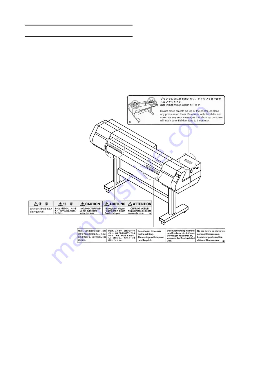
POSITION OF THE WARNING  LABEL

This device is adhered with a warning label at two locations. Be sure to fully understand the warning

given on the labels.

In the case where any of the warning label has become so soiled that the warning message is illeg-

ible or has come off, purchase a new one from your local distributor or our office.

Содержание JV4 Series

Страница 1: ...AKI ENGINEERING CO LTD TKB Gotenyama Building 5 9 41 Kitashinagawa Shinagawa ku Tokyo 141 0001 Japan Phone 81 3 5420 8671 Fax 81 3 5420 8687 URL http www mimaki co jp E mail trading mimaki co jp D2005...

Страница 2: ......

Страница 3: ...anufactured with damaged medium Please be noted that MIMAKI ENGINEERING CO LTD shall have no liability for any debts unearned profits and any claims from any third party resulting from the use of the...

Страница 4: ...om the product Use a power line for the receiver that is not shared with the product FCC Statement USA This equipment has been tested and found to comply with the limits for a Class A digital device p...

Страница 5: ...ation and maintenance of Model JV4 Series Color Ink Jet Plotter hereinafter referred to as the device Please read and fully understand this Instruction Manual before putting the machine into service I...

Страница 6: ...suitable for outdoor print on large sized color sign displays e g signboards Water soluble dye ink This type of ink has good color development and is most suitable for indoor print such as posters Di...

Страница 7: ...ing operation of the device HIGH SPEED INTERFACE The IEEE 1394 interface allows for high speed data reception from the computer PLOTTING FOR ARTWORK OF SCREEN PRINTING By using the exclusive block cop...

Страница 8: ...ates the case where some phenomenon that requires a CAUTION sign including DANGER and WARNING signs exists A concrete precaution precaution against an electric shock in thecase of the sketch given on...

Страница 9: ...r repair your device by yourself since it is very dangerous for you to do so Roll paper Roll paper is heavy Be careful not to drop it If you drop it on your foot or any other part of your body persona...

Страница 10: ...of ink to fall abruptly down on the medium during printing If this phenomenon takes place be sure to clean up the head See Chapter 4 Maintenance functions Periodic exchange parts There are some parts...

Страница 11: ...ting quality would be poor Be sure to store ink cartridges in a cold and dark place Never replenishes the ink cartridge with ink Using any ink type other than the exclusive one can cause a trouble Rem...

Страница 12: ...HE PARTS UNDER THE FRONT COVER 1 7 CARRIAGE 1 7 CAPPING STATION 1 8 THE PINCH ROLLER AND THE FEED ROLLER 1 8 THE MEDIUM SENSOR 1 9 CUTTER BLADE AND CUTTING LINE 1 10 HEAD HEIGHT ADJUSTMENT ROD AND ADJ...

Страница 13: ...ROLL ON THE DEVICE 1 37 SETTING CUT SHEET MEDIUM ON THE DEVICE 1 42 SETTING A BOARD MEDIUM ON THE DEVICE 1 44 SPECIFYING THE SCOPE OF PLOTTING ON THE MEDIUM USED EFFECTIVE PLOTTING AREA 1 46 CHANGING...

Страница 14: ...Y OF SETTINGS BY THE COMPUTER OR THE DEVICE PRIORITY 3 11 INCREASING DECREASING THE RIGHT AND LEFT MARGINS OF THE MEDIUM 3 13 WHEN USING THE DEVICE IN AN EXTREMELY DUSTY OR DRY PLACE REFRESH 3 15 SETT...

Страница 15: ...WHEN CHARGING INK DIFFERENT FROM THE ONE IN USE INK CHANGE 4 19 FOR PLOTTING WITH ONLY ONE INK STATION USE HEAD 4 21 COUNT THE AMOUNT OF REMAINING ROLL MEDIA MEDIAREMAIN 4 22 WHEN THE WASTE INK TANK...

Страница 16: ...e is explained The pages of each chapter are given serial numbers starting from 1 Notes to sentences caution on device operation and hints for effective use of the device are given The item to select...

Страница 17: ...lay is shown in characters in a box as shown at right Operate the device according to the explanation of the operation procedure and the content of display on the LCD In this instruction manual each s...

Страница 18: ...THE APPLICATION FUNCTIONS This chapter describes the application functions of the device such as the function menu for setting plotting conditions CHAPTER 4 MAINTENANCE FUNCTIONS This chapter describe...

Страница 19: ...FRONT COVER 1 7 UNPACKING AND ASSEMBLING 1 12 CONNECTING THE CABLES 1 18 SWITCHING ON OFF THE POWER SUPPLY 1 20 FRONT COVER 1 22 INK CARTRIDGES 1 23 INITIAL SETTING OF INKS 1 26 SETTING INK CARTRIDGES...

Страница 20: ...space required not only for the device itself but also for plotting operation Model Width Depth Height Gross weight JV4 130 2410 mm 730 mm 1205 mm About 140 Kg JV4 160 2740 mm 730 mm 1205 mm About 15...

Страница 21: ...nents in it If you find any missing accessory or damaged one contact your local dealer or MIMAKI office Main unit Take up device Left stand Right stand Stay Medium support 4 pcs Plotting film for adju...

Страница 22: ...cable Hexagonal wrench L Phillips screwdriver M4 cap bolt for fitting the M8 cap bolt long take up device 4 pcs 8 pcs JV4 180 for fitting the stay 2 pcs M8 cap bolt Short IEEE1394 Driver for fitting...

Страница 23: ...aying set items etc 7 Maintenance cover This is the carriage cover During maintenance of the station See page 4 8 open it by loosening the screws 8 Clamp lever It is made to go up down the pinch rolle...

Страница 24: ...l holder is inserted in the right and left core of roll medium to hold the roll medium The roll holder is applicable to diameter of medium cores with 2 and 3 inches 4 Paper roll setting bar This bar f...

Страница 25: ...t according to the thickness of the medium used The carriage moves during plotting medium cutting and medium detection When cleaning the interior of the capping station execute the STATION MAINTENANCE...

Страница 26: ...ND THE FEED ROLLER This device retains a medium with the pinch roller and the feed roller During plotting operation the feed roller feeds the medium forward While the device is not being used keep the...

Страница 27: ...hand part of the platen THE MEDIUM SENSOR The medium sensors detects the presence of the medium and the medium length There is a medium sensors on the platen Set up medium to cover medium sensor at t...

Страница 28: ...tter unit for cutting off the medium that has been plotted on The cutting line along which to cut off the medium is shown below For the method of cutting a medium see Cutting by Hand page 2 7 or Autom...

Страница 29: ...g the head height the heads may get caught on the medium causing damage to the heads For the method of head height adjustment see Adjusting the Head Height Height Adjustment page 1 34 in Chapter 1 Set...

Страница 30: ...00 kg Perform the assembly work by at least four persons to ensure safety Exercise added care not to drop the main unit on your feet 1 Remove the four bolts that fixes the packed pedestals and packed...

Страница 31: ...e side having a groove for fitting the stay coming inside 4 Fit the stay to each of the stands Fit the stay to the stands Insert the stay into the groove of each stands and tighten the screw using the...

Страница 32: ...in the tops of the stands Fix the device to the stands with the screws from under the stands tops The device is very heavy Take care that it does not fall it is very dangerous INSTALL THE TAKE UP DEVI...

Страница 33: ...page 4 8 through 4 14 Opening the maintenance cover during plotting interrupts image plotting and disables continu ous processing INSTALLING THE WASTE INK TANKS Different size of waste ink tank is at...

Страница 34: ...posi tions Determine the fixing position of the left hand roll holder according to the thickness of the roll core used then fix it with the screw 2 inch roll core Use the outer fixing hole 3 inch rol...

Страница 35: ...e sure to lock the caster stoppers Method of moving the device When moving the device it must be held up by at least two persons as illustrated at right The cover of the device may break if it is pres...

Страница 36: ...sult When Windows 2000 is used IEEE 1394 When the computer is operated with Windows 2000 use an IEEE 1394 interface cable to connect the computer and the device together It is possible to use an IEEE...

Страница 37: ...nded receptacle If not there is a fear of arising electric shock hazards and damage to the device Be sure to turn off the power switch of the device in prior to the connection of the power cable 1 Con...

Страница 38: ...and the initial operation of the device is performed 2 The message Please Wait appears flashing on the LCD 3 The device enters the LOCAL mode 4 Turn on the power to the connected devices such as a com...

Страница 39: ...f while the device is engaged in plotting the head may fail to be retracted in the capping station If the head is left without capped for an extended period of time the nozzle will be clogged with dus...

Страница 40: ...ng the front cover during plotting interrupts image plotting and disables continuous processing CAUTIONS DURING OPERATION STEP 1 When opening the cover during plotting the message shown on the right w...

Страница 41: ...between ink station and head row The F row ink station supplies ink to the front row F row of heads The R row ink station supplies ink to the rear row R row of heads Remember these relationships when...

Страница 42: ...igment ink PigOG A pigment based ink having good weather resistance The conventional pigment based ink Having excellent light fastness this type of ink is most suitable for outdoor print on large size...

Страница 43: ...in the room temperature for three hours or more before using it Be sure to thoroughly consume the ink in the ink cartridge once it is opened within six months If an extended period of time has passed...

Страница 44: ...Orange Green Dye Water soluble dye ink Sub Disperse dye ink 3 Move the cursor by pushing the JOG keys and 4 By pushing the JOG keys and specify the type of ink set in the F row ink station 5 Push the...

Страница 45: ...ing information and changing the heads used When two ink sets of the same type are loaded to two ink stations if INKnearEND occurs during plotting only one ink set is used Therefore the PRINT CONT fun...

Страница 46: ...ter soluble pigment ink Orange Green set Setting water soluble pigment ink Light set and water soluble dye ink Setting water soluble pigment ink Orange Green set and water soluble dye ink Setting wate...

Страница 47: ...ter the appropriate ink type for each ink station See page 1 26 The registered ink type is necessary when checking the plotting information and changing the heads used LC LC LM LM Y M C K Y M C K Disp...

Страница 48: ...P 1 Either of the messages shown above is dis played on the LCD during plotting When INKnearEND appears the local mode is entered and the operation stopped each time plotting of a single data is compl...

Страница 49: ...k film Canvas Tarpaulin Waterproof olefinfilm Board Sizes of medium that can be used The size of medium varies according to model of the JV4 series Refer to the following table for the model used Medi...

Страница 50: ...dity The medium have to be left in the atmosphere in which they are to be used for 30 minutes or more after unpacked Curled medium Avoid the use of curled medium They can be a cause of a medium jam If...

Страница 51: ...arly the same in height as the platen top surface on the front and rear sides of the device Otherwise it can happen that the printing surface of the board makes contact with the head or the board is n...

Страница 52: ...t Adjust the head height before setting the medium on the device If an attempt is made to adjust the head height with the medium kept set on the platen the medium gets caught on the carriage during ca...

Страница 53: ...urn the head height adjustment screw in the direction shown and move the head downward With the head height adjustment rod kept pushed lower the head till the tip of the rod makes contact with the sur...

Страница 54: ...even when the head is raised To avoid fluffing of the medium surface warp of the medium edge or waving of the medium during plotting the distance between the head and the printing surface of the mediu...

Страница 55: ...on your foot When setting the medium be sure to check that the head height has been properly adjusted See page 1 34 STEP 1 Pull up the clamp lever at the back of the device The roll holder is prevente...

Страница 56: ...the roll medium on the medium support bar the position of roll holder can be adjusted easily 4 Insert the right hand roll holder into the core of the roll medium After inserting the roll holder comple...

Страница 57: ...ers and pull it to the front of the device 7 Push the clamp lever at the back of the device Fix the roll medium with the pinch rollers to prevent it from slipping out 8 Pull up the clamp lever at the...

Страница 58: ...r and the platen While pulling the roll paper from side to side evenly clamp the lever See page 3 25 If the roll medium used is wide the edges of the paper may get loose from the platen during plottin...

Страница 59: ...parent or plotted medium is set the following message appears on the LCD and the medium may not be detected For the method of setting up the medium detection function see page 3 16 When the device is...

Страница 60: ...dium take care that it is set straightforward The medium guides provided on the platen help set the medium correctly See page 1 9 STEP 1 Open the front cover 2 Push up the clamp lever The clamp lever...

Страница 61: ...the initial operation the device enter the LOCAL mode See page 1 20 6 Push down the clamp lever at the front of the device 7 Push the key The carriage moves to detect the medium Then the device enters...

Страница 62: ...34 Prepare stands for preventing the board from hanging down See page 1 33 When the board is used set BOARD detection to ON See page 3 17 STEP 1 Open the front cover 2 Push up the clamp lever The cla...

Страница 63: ...enter the LOCAL mode See page 1 20 After setting the medium on the device The medium can be detected after setting it and push down the clamp lever at the front of the device Turn ON the BOARD settin...

Страница 64: ...E DEAD SPACE The dead space may be changed as required The effective plotting area can be changed by changing the dead space For the method of setting a dead space see page 3 13 0 mm 5 mm Medium feedi...

Страница 65: ...rom the right end INITIAL VALUE OF ORIGIN As the ORIGIN position the initial value corresponding to the head and operating mode is set The origin positions shown below are specified until new origin i...

Страница 66: ...deciding the origin push the ENTER key The origin has been changed The effective plotting area is displayed on the LCD and the device enters the LOCAL mode When a roll medium is used X medium length...

Страница 67: ...the medium with its plotting face faced out OFF The take up device will not wind the medium REVERSE The take up device winds the medium with its plotting face faced in SETTING THE TORQUE LIMITER There...

Страница 68: ...er fails to be sent smoothly A TAPE STOP FOR MEDIUM CORE When a medium broad in width is used it may be hard to wind around the medium core 2 Then place two tape stops on the left and right edges as s...

Страница 69: ...plication functions understand how to use the basic functions of the keys on the operation panel and the modes in which the menus are displayed on the LCD TABLE OF CONTENTS OPERATION 2 2 PLOTTING AN I...

Страница 70: ...t lights up in green when the power to the device is turned on DATA CLEAR key Used to erase the data that has been input to the device REMOTE key It is used to change the operation mode between the RE...

Страница 71: ...eparations for plotting operation are made When the power is switched on and the detection of a medium is completed the device enters the LOCAL mode In this mode it is possible to perform the followin...

Страница 72: ...local mode on the LCD 3 To set up a specific function from the operation panel follow the procedure shown below 1 Push the appropriate operation key on the operation panel 2 Select the desired setting...

Страница 73: ...The amount of ink that remains is displayed LOCAL INKremain 1 2 3 4 5 6 7 8 9 0 1 2 The type of ink being used is displayed LOCAL INK TYPE R PigOG F PigOG The height of head is displayed LOCAL Head H...

Страница 74: ...n can be confirmed See page 3 4 5 Receive data from the computer The plotting conditions that have been set for the data are displayed For the method of data transmission see the manual for the output...

Страница 75: ...switching off the power is explained below When Auto Cut has not been specified See page 3 10 cut off the medium using the following procedure If the head height is 3mm or more cutting is not possibl...

Страница 76: ...form the test plot on a cut sheet medium use a medium whose size is A4 or larger with placed in landscape configuration STEP 1 The device enters the LOCAL mode Push the REMOTE key and put the device b...

Страница 77: ...imes clean the ink station interior See page 4 9 Do not CLEANING strong regularly because it may absorb the head By the result of test pattern plotting select a head to be cleaned Corresponding heads...

Страница 78: ...n status is displayed with in the second line 7 The device enters the LOCAL mode CLEANING R 1 2 3 HEAD SEL F 1 2 3 LOCAL width 1272mm CLEANING TYPE normal CLEANING TYPE soft CLEANING TYPE strong CLEAN...

Страница 79: ...nce works after turning off the power switch and detaching the power cable If not unexpected troubles can arise Do not use benzine thinner and chemical agents containing abrasives Such materials can d...

Страница 80: ...ttom of the head periodically using the supplied brush dampened with water See step 11 on page 4 14 Be careful not to rub the head nozzle during cleaning Damaged head nozzle may cause inferior ink dis...

Страница 81: ...you can set plotting conditions on the device side and put the device into operation By using the application functions you can set plotting conditions appro priate to data that is provided for the p...

Страница 82: ...t is necessary to understand the proper sequence of key operations In Set up of the function menu allocate plotting methods to be set to Types 1 to 4 before detailed setting of the individual plotting...

Страница 83: ...or the FUNCTION mode Check also that the mode displayed on the LCD is either LOCAL or FUNCTION See page 2 3 SETTING THE DISPLAY LANGUAGE Set the language in which to display characters on the LCD Engl...

Страница 84: ...ating plotting conditions to a particular type is explained STEP 1 Make sure that the mode is LOCAL mode See to Page 4 3 2 Push the FUNCTION key 3 Push the ENTER key 4 Select any of Types 1 through 4...

Страница 85: ...mage quality FINE High image quality and low plotting speed HIGHspd High plotting speed and slightly inferior image quality STEP 1 Select a type see page 3 4 Here select Type 1 2 Push the ENTER key 3...

Страница 86: ...uivalent to 1440dpi OFF The resolution is not extended increased Performs printing with the resolution established by command STEP 1 Select a type see page 3 4 Here select Type 1 2 Push the ENTER key...

Страница 87: ...ement of the carriage Image quality slightly deteriorates since emphasis is placed on printing carriage STEP 1 Select a type see page 3 4 Here select Type 1 2 Push the ENTER key 3 Push the ENTER key 4...

Страница 88: ...shed surface As a result the ink head may rub the medium sur face to stain the medium or to cause paper jamming breaking the head STEP 1 Select a type see page 3 4 Here select Type 1 2 Push the ENTER...

Страница 89: ...the ENTER key 5 Set a drying time after the scanning by push ing the JOG keys and This is the drying time from the instant at which the carriage returns to the capping station till the instant at whi...

Страница 90: ...n after the plotting is completed STEP 1 Select a type see page 3 4 Here select Type 1 2 Push the ENTER key 3 Push the and key until the display gives the indication AUTO CUT 4 Push the ENTER key 5 Se...

Страница 91: ...OT The plotting operation is performed with priority given to the plotting conditions set on the device Priority needs to be specified for each of the following items PRINT MODE MEDIA COMP INK LAYERS...

Страница 92: ...15 Push the and key to select priority HOST and PLOT Here select PLOT 16 Push the ENTER key 17 Push the and key to select priority HOST and PLOT Here select PLOT 18 Push the ENTER key 19 Push the END...

Страница 93: ...type See page 3 4 Here select Type 1 2 Push the ENTE key 3 Push the and key until the display gives the indication MARGIN 4 Push the ENTER key 5 Push the ENTER key 6 Set a dead space by pushing the JO...

Страница 94: ...n LEFTmargin 6 Push the ENTER key 7 Set a dead space by pushing the JOG keys and You can set a dead space in the range 9 mm to 95 mm in increments of 1 mm Here set 10mm 8 Push the ENTER key 9 Push the...

Страница 95: ...1 Frequency of refreshing is normal LEVEL 2 Frequency of refreshing is slightly high LEVEL 3 Frequency of refreshing is high STEP 1 Select a type See page 3 4 Here select Type 1 2 Push the ENTER key...

Страница 96: ...hod when a roll medium is used Only the width of a medium will be detected When the device power is switched on the device detects only the medium width automatically STEP 1 Select a type See page 3 4...

Страница 97: ...e 1 2 Push the ENTER key 3 Push the and key until the display gives the indication MEDIA SET 4 Push the ENTER key 5 Push the and key until the display gives the indication BOARD 6 Push the ENTER key 7...

Страница 98: ...l suction LOW Suction to be applied to the medium will be lowered when nonflammable cloth is used STEP 1 Select a type See page 3 4 Here select Type 1 2 Push the ENTER key 3 Push the and key until the...

Страница 99: ...s are expressed in millimeters INCH Numerics are expressed in inches STEP 1 Select a type See page 3 4 Here select Type 1 2 Push the ENTER key 3 Push the and key until the display gives the indication...

Страница 100: ...set PigOG Water soluble pigment Orange Green set Dye Water soluble dye Sub Disperse ink for sublimation transfer If the same type of ink is set in the ink stations on both sides the type of ink canno...

Страница 101: ...a record of plotting data STEP 1 Select a type See page 3 4 Here select Type 1 2 Push the ENTER key 3 Push the and key until the display gives the indication MODE STAMP 4 Push the ENTER key 5 Set a ty...

Страница 102: ...ode needs to be specified for each of the following two items Specifying image quality in ARTWORKmode Specify an image quality in ARTWORKmode as follows STANDARD The quality of image improves from 1 2...

Страница 103: ...density by pushing the JOG keys and Select NORMAL or THIN Here select THIN 10 Push the ENTER key 11 Push the END key twice and the menu returns to the LOCAL mode TYPE 1 ARTWORKmode ON TYPE 1 ARTWORK D...

Страница 104: ...t cleaned automatically STEP 1 Select a type See page 3 4 Here select Type 1 2 Push the ENTER key 3 Push the and key until the display gives the indication AUTO CLEAN 4 Push the ENTER key 5 Set a AUTO...

Страница 105: ...set by 0 1 m If the ink is almost empty this function will not be performed A normal pattern may not be obtained because of the head status etc even after performing cleaning STEP 1 Select a type See...

Страница 106: ...Push jog key or to select an interval to perform cleaning 10 Push the ENTER key 11 Push the END key twice and the menu returns to the LOCAL mode LOCAL width 1272mm TYPE 1 INTERVAL 1 0m TYPE 1 INTERVAL...

Страница 107: ...n the two ink stations this function cannot be used since PRINT CONT is not displayed on the LCD STEP 1 Select a type See page 3 4 Here select Type 1 2 Push the ENTER key 3 Push the and key until the...

Страница 108: ...the ENTER key 5 Push the ENTER key Test plotting for correction of the medium feed rate starts Seven types of medium correction patterns are plotted 6 Enter a correction value from the output pat tern...

Страница 109: ...best effect can be obtained while checking the result The unit of the correction value is the same as in MEDIA COMP in the LOCAL mode 5 Press the ENTER key Confirm the medium feed rate before saving i...

Страница 110: ...pe See page 3 4 Here select Type 1 2 Push the ENTER key 3 Push the and key until the display gives the indication SETUP RESET 4 Push the ENTER key 5 Push the ENTER key The current plotting conditions...

Страница 111: ...describes the functions that help solve the problem of dete rioration in image quality and replace a waste ink tank and worn cutter blade The device needs maintenance when it is left out of operation...

Страница 112: ...functions of the device it is necessary to understand the proper sequence of key operations FUNCTION See Chapter 2 HOW TO USE THE BASIC FUNCTION SET UP FUNCTION LIST MAINTENANCE DATA DUMP PRINT adjust...

Страница 113: ...tion on the operation panel You have to understand how to invoke the desired maintenance function to carry out maintenance STEP 1 Put the device into the LOCAL mode Push the REMOTE key and put the dev...

Страница 114: ...nguage specified on the operation panel 3 PRINTadjust Indicates a correction value for dot position 4 REPLACE COUNTER Indicates the number of times the ink cartridges are replaced 5 VERSION Indicates...

Страница 115: ...ut data commands on a sheet of paper use A4 or larger size with the long side set horizontally DATA DUMP automatically feeds line according to the size of paper used STEP 1 Put the device into the LOC...

Страница 116: ...Push the ENTER key Plotting of the test patterns for the correction of dot position starts There are seven types of test patterns that are plotted 5 Push the JOG keys and to correct the dot position o...

Страница 117: ...ition correction value on Patterns 1 to 7 and then terminate dot position correction 8 Push the END key twice and the menu re turns to the LOCAL mode MAINTENANCE PATTERN1 0 0 MAINTENANCE PATTERN2 0 0...

Страница 118: ...ush the ENTER key Carry out the following maintenance of the station interior 6 Open the maintenance cover then perform the following maintenance works for the station interior For the method of maint...

Страница 119: ...ing is not corrected or nozzles are clogged even after the cleaning function is executed or when the plotter is left unused for a long period of time STEP 1 Move the carriage Execute the station maint...

Страница 120: ...blades according to the relevant national and local ordinances in which the device is used STEP 1 Move the carriage Execute the station maintenance CARRIAGE OUT Refer to step 1 to 6 on page 4 8 2 Open...

Страница 121: ...e of felt and the rear side is made of rubber Do not rub the felt side with a swab Instead press the swab against the felt side surface to remove dirt Rubbing the felt side surface will make it fluffy...

Страница 122: ...ed below 3 Clean the wiper guide shaft using a cotton bud or cloth If dirt is hard to remove use a cotton bud of cloth damepened with water Extremely dirty wiper guide shaft may cause operation failur...

Страница 123: ...e wipers are cleaned and tells when to replace them When the message Replace Wiper is displayed on the LCD replace the wipers with new ones The message Replace Wiper is displayed while the device is i...

Страница 124: ...r shall be avoided It can cause the nozzle to be clogged Insert the wiper so that its felt side surface is placecd on the left as viewed from your position 10 Clean the wiper guide shaft using a cotto...

Страница 125: ...um detection display will appear on the LCD after the initialization 16 The device enters the LOCAL mode ADJUSTING THE HEAD HEIGHT WHEN THE MEDIUM USED IS CHANGED HEAD HEIGHT See page 1 34 ADJUSTING T...

Страница 126: ...e indication ARTWORKtest 4 Push the ENTER key 5 Push the ENTER key The ARTWORK test starts During the test plotting the two heads using black K are subjected to the nozzle check 6 Check drawing failur...

Страница 127: ...quality and plotting density that have been specified in the ARTWORK mode are displayed See page 2 6 3 22 STD shows STANDARD QUA shows QUALITY It becomes STD 3 NORMAL when the artwork mode isn t chose...

Страница 128: ...rtions in fill patterns If there are unpainted dots execute the cleaning function see page 2 9 Repeat Steps 6 through 9 depending on the result of the test plotting and the medium used 10 Push the END...

Страница 129: ...G CO LTD shall have no liability for any trouble that arises when using any ink cartridge or ink other than the genu ine MIMAKI brand ones For ink replacement please purchase the optional Washing Liqu...

Страница 130: ...ischarged in step 8 Washing is started automatically 10 Take out the washing liquid cartridge from the ink station Discharge of the washing liquid is started 11 Repeat steps 9 and 10 12 Install new in...

Страница 131: ...for plotting When different ink types are loaded as in the Setting for 1Way high speed printing mode the USE HEAD function cannot be set because it is not displayed in the menu See page1 28 STEP 1 Put...

Страница 132: ...r Plot the adjustment pattern with REST ADJUST and input the length of the pattern to reduce the counting error Adjustment pattern 500mm a b STEP 1 Enter to the function mode See page 4 3 2 Push the E...

Страница 133: ...d to input the length inbetween a and b by 0 1mm 11 Push the ENTER key 12 Push the END key three times to return to the LOCAL mode When MEDIAremain is set to ON the amount of remaining roll media is s...

Страница 134: ...o replace the waste ink tank visually check the level of waste ink in the tank STEP 1 Remove screws from the waste tank guard 2 Open the waste tank guard 3 Replace the waste ink tank with a new one Pu...

Страница 135: ...sures to be taken in the case where an abnormal phenomenon arises on the device and where an error mes sage is given on the display TABLE OF CONTENTS BEFORE TAKING A PHENOMENON AS A SIGN OF FAILURE 5...

Страница 136: ...en properly connected to the power outlet and the computer THE DEVICE CANNOT PERFORM PRINTING This occurs when the data is not being transmitted to the device properly It can also occur when any of th...

Страница 137: ...is set improperly Are you using midium specific to the device Yes Are you using midium that has neither curls nor bent ends Yes Does the midium hang over along the platen Use midium specific to the de...

Страница 138: ...ure If slip of paper is present in the head path for example above the curl stopper remove it CHARACTERS OF LIST PAGE 4 4 FLUCTUATE DOUBLY OR TRIPLY INTO PAPER FEED DIRECTION Corrective measure Conduc...

Страница 139: ...he ink station The amount of ink remaining in the ink cartridge is insufficient The ink cartridge has run out of ink Time to replace the wiper in the capping station with a new one has come Attach the...

Страница 140: ...bnormal temperature is detected Trouble with detection of linear encoder Control circuit board is defec tive FPGA Error HDC Error The device has received data other than command data A parameter outsi...

Страница 141: ...rcurrent error on the Xmotor has been detected Overcurrent error on the Ymotor has been detected Warning message Cause Corrective measure Turn off the power to the device and turn it on after a while...

Страница 142: ...g message Cause Corrective measure Turn off the power to the device and turn it on after a while If the same error message appears again on the LCD contact your local distributor to call for service T...

Страница 143: ...appendix describes the specifications and components the device function menu structure TABLE OF CONTENTS BASIC SPECIFICATIONS A 2 SPECIFICATION FOR INK A 4 FUNCTION MENU STRUCTURE A 5 POSITION OF THE...

Страница 144: ...er Glossy PVC Matte medium Mat PVC Tarpaulin Back lit film Cloth Nonflamable cloth Other Artwork film Canvas Tarpaulin Waterproof olefin film Board Max Printing width Width 1371 mm Width 1600 mm Width...

Страница 145: ...ing standby Less than 56 dB Noise during continuous printing Less than 66 dB Noise during discontinuous printing Less than 70 dB Safety Standard FCC ClassA Power AC 100 240 V 120 W or less Power consu...

Страница 146: ...e ink Blue ink cartridge SPC 0256BI Magenta ink cartridge SPC 0256M Yellow ink cartridge SPC 0256Y Light Blue ink cartridge SPC 0256Lbi Light magenta ink cartridge SPC 0256Lm Contents of inkcartridge...

Страница 147: ...NCH INCH MM INK TYPE Pigcm PigOG Dye Sub MODE STAMP OFF ON ARTWORKmode OFF ON AUTO CLEANING OFF ON AUTO CLEANING2 OFF ON CL Type SOFT NORMAL STRONG INTERVAL 0 1m 100 0m PRINT CONT OFF ON MEDIA COMP 50...

Страница 148: ...ning label at two locations Be sure to fully understand the warning given on the labels In the case where any of the warning label has become so soiled that the warning message is illeg ible or has co...

Страница 149: ......

Страница 150: ...D200571 2 60 16022006...

Страница 151: ......

Страница 152: ...PrintedinJapan MIMAKI ENGINEERING Co Ltd 2006...

Отзывы: