


20
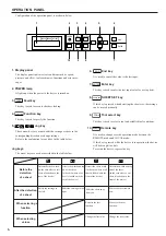
Item
Description of function
Reference page
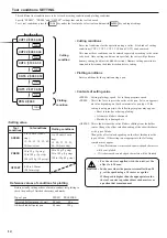
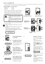
Origin select
The origin is a reference point of data to be cut (plotted). To start cutting (plotting),
be sure to specify an origin in prior.
Cutting area setting
*
An area in which the device performs cutting (plotting) is specified.
The area that has a diagonal line extending from the origin and a given the point is
the effective cutting area. If you tilt the sheet set lever away from you, the cut area
specified will be cleared.
Axis alignment
*
Aligns the axis of the sheet to be used with that of the device.
Functions invoked with specific keys
Item
Description of function
Reference page
Tool select
Sets a tool to be used to a cutter or pen.
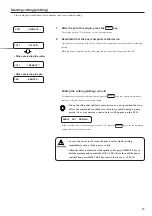
Sheet feed
Feeds the sheet by the amount to be used. In the case where a roll sheet is used or
a long-dimension data is to be cut, the sheet has to be fed by the length to be used
to provide an allowance. In addition, displacement of the sheet can be checked by
feeding the sheet. Enter the length to be fed by sheet feed using a jog key.
Sheet set
Sheet is detected again at the time of sheet replacement.
Functions
Item
Description of function
Reference page
Data clear
*
Clears data being cut.
No. copies
*
Performs cutting according to the received data on two or more sheets.
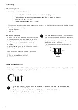
Square cut
*
Performs cutting of a square to verify that cutting conditions are appropriate.
Distance compensation
*
Compensate an error in cutting length.
INTERFACE
Establishes communication conditions in accordance with the host computer in the case
where interface is used.
CUT MODE
*
Specifies cutting quality. Change cutting quality when smooth curve or fine finish is
desired.
ORIGIN SELECT
Establishes an origin in accordance with the command specification of application
software used.
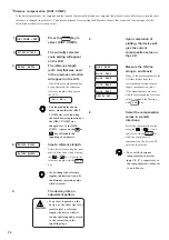
ROTATION
*
Specifies the location of origin and direction of coordinate
axis.
4 types of rotation based
on the coordinate system and moving of the origin point can be made by combination.
DIVISION CUT
*
Cuts data that exceeds the sheet width with divided appropriately.
PROPRITY
This function is used to specify the setting that is given priority in terms of the following
tool setting values; either the setting established on the device or that established on the
host computer is given priority.
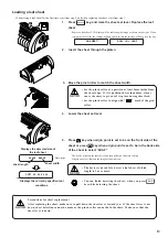
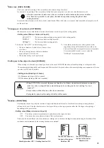
SHEET SENSOR
Turns off the sheet sensor function. The sheet sensor detects the presence/absence of a
sheet and the sheet length. Two sheet sensors are mounted on the platen. In the case where
any of the following types of sheet is used, the sheet sensors will not be able to detect it to
give the error message shown below.
•Transparent sheet that does not reflect the light
coming from the sheet sensor. •The sheet of which wrong side is black that does not
reflect the light coming from the sheet sensor. In this case, cutting is enabled by setting
the [SHEET SENSOR] function contained in the SET UP of FUNCTION to OFF.
**NO SHEET **
MM/INCH
Changes over the unit of length to be displayed.Unit for jog operation, and unit for sheet
size display and distance correction can be changed.
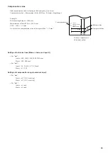
EXPAND
*
When cutting is to be made up to the edge of a sheet, the use of EXPAND function will
enable plotting over the pinch roller, thus maximum plotting width can be expanded.
JOG STEP
Specifies an amount of travel corresponding to a press on a jog key (arrow key).
SETUP RESET
Initializes the current tool setting.
Sample cut
Performs cutting of characters “Cut” to determine whether or not the device is faulty.
Dump execution
Plots data sent from the host computers in the ASCII data format. To execute the dump,
be sure to use a pen as the tool.
List
Plots tool conditions or function setting conditions. To execute the list, be sure to use a
pen as the tool.
Display
Changes over the language to be displayed on the LCD.
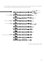
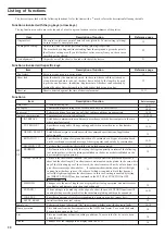
Listing of functions
The device is provided with the following functions. As for the items with a
*
mark, refer to the description following the table.
Functions invoked with the jog keys (arrow keys)
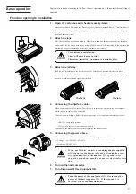
The jog function is used to move the top end of a tool to a given location to set coordinates of the plotter.
SET
UP
15
22
14
12
12,13
18,21
18,22
16,18
19,23,24
8
19,21
19
19,21
19,25
19
19
19
19,21
19
16,18
18
18
18
21
6


