4
Checking the accessories
Leg 4 piece
Screw 8piece
(for roll hanger
mounting/for legs)
Adapter (Only 100V)
Configuration of the main unit
Front of the main unit
Roll stay 2 piece.
Power cable
Operation Manual
FineCut
Pen adapter, 1 piece
Main unit
Cutter holder 1piece
Water-ink ball-point pen
1piece
Roll bar 1piece
L shaped wrench, 1 piece
Cap, 1 piece
Name of each part of the equipment and their functions will be explained. Try to
memorize the names as quickly as possible and master their usage.
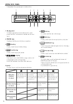
Operation panel
The device is operated and functions are
set on the operation panel.
Tray
Small stuff can be placed on it.
Note that the cutter has to be kept out of
reach of children since it can be dangerous.
Do not put a heavy stuff on a tray.
The cover will be deformed and then be
contact into carriage.
Carriage
The carriage travels from side to
side with holding a tool. It is also
used to raise/lower the tool.
PINCH ROLLER
SETTINGS Mark
The marks indicate the locations
at which the pinch rollers are set.
Platen
The sheet moves along the platen.
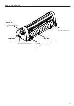
Grid roller
The grid rollers operate in combination
with the pinch rollers to feed out the sheet.
Pen line rubber
The device performs cutting or plotting on the pen line
rubber.
RS-232C interface connector
The RS-232C compatible interface connector. It is
connected to the RS-232C connector of the host computer
via an interface cable.
8 bit parallel interface
connector
The Centronics compatible interface
connector. It is connected to the
printer connector of the host
computer via an interface cable.
Pinch roller
The pinch rollers can be moved to
the right or left to adapt to the size
of sheet to be used.
The pinch rollers feed out the sheet
while pressing it against the
corresponding grid rollers.
Sheet sensor
It detects the presence of the
sheet and sheet length.
The articles illustrated below are supplied with your device as accessories.
Check them up for correct quantities and appearance.
If you should find any fault, please contact your distributor.


