background image

APPAREL CUTTING PLOTTER

CG-100AP

INSTRUCTION MANUAL

MIMAKI ENGINEERING CO., LTD.

TKB Gotenyama Building, 5-9-41, Kitashinagawa-ku, Tokyo 141, Japan

Phone:  +81-3-5420-8671      Fax:  +81-3-5420-8687

Chapter 1  Set-up

The procedures for the initial set-up of the UNIT from unpacking to starting of

the service operation shall be explained herein in detail.

Accordingly, the MANUAL must be read throughly when you purchase the

UNIT.

Chapter 2  Basic Operation

The basic procedures for preparation of the paper patterns shall be explained

in accordance with the flow of the operation.

Chapter 3  Application Functions

Useful functions as the application operations other than the above-mentioned

basic operations shall be explained.

Chapter 4  Self Diagnosis Functions

The self diagnosis functions to search probable causes of abnormal operations

of the UNIT in plotting and cutting shall be explained.

Chapter 5  Trouble Shooting and Possible Remedy

The schemes for trouble shootings and possible remedies for failed operations

shall be explained.

Chapter 6  Appendix

The explanations shall be provided for the merit of the pens to be used, main-

tenance of the UNIT, specification of the UNIT and so forth.  In addition,

appropriate forms (Additional Purchase Order Sheet, Inquiry Sheet and etc.)

are involved.

D200310

Содержание cg-100AP

Страница 1: ...low of the operation Chapter 3 Application Functions Useful functions as the application operations other than the above mentioned basic operations shall be explained Chapter 4 Self Diagnosis Functions The self diagnosis functions to search probable causes of abnormal operations of the UNIT in plotting and cutting shall be explained Chapter 5 Trouble Shooting and Possible Remedy The schemes for tr...

Страница 2: ... radios located near by the UNIT may be significantly influenced from radio distur bances such as noise the trouble shooting for a radio disturbance if any shall be conducted by turning ON OFF the power of the UNIT with leaving theinfluenced equipment activated status The noise corresponding to the power turning ON OFF of the UNIT indicates that there is the noise source in the UNIT The radio dist...

Страница 3: ...l the time for your routine operation The MANUAL consists of the following contents Remarks Please contact with the nearest our Branch Office Distributor or Marketing Department of the COMPANY for any question for contents of the MANUAL The MANUAL may be revised from time to time for improvement of the contents without prior notice for which your acknowledgement would be apprecia ted When the MANU...

Страница 4: ...CHAPTER 1 SET UP CONFIGURATION NAME AND FUNCTION 1 2 PACKING CHECK 1 4 ASSEMBLY OF PLOTTER 1 9 General Description 1 9 Assembly 1 10 SET UP OF PLOTTER 1 16 CONNECTION OF CABLES 1 18 General Description 1 18 Interfaces 1 18 Connection of Interface Cable RS 232C Cable 1 19 Connection of Interface Cable Parallel Cable 1 20 Connection of Power Cable 1 22 POWER ON OFF 1 23 Turning the power ON 1 23 Tur...

Страница 5: ...es of the Tools 1 40 Types of Pens Ball Pen Plastic Pen Ceramic Pen 1 41 Details of Mechanical pencil 1 42 Plotting Function of Mechanical pencil 1 43 How to load Lead into the Mechanical pencil 1 44 Restore from Clogged Lead 1 45 Service Life of Mechanical pencil 1 47 Cutter 1 49 MEDIA 1 52 Types of Media 1 52 Usable Media in the UNIT in Size 1 53 Handling of Paper 1 53 CHAPTER 2 BASIC OPERATION ...

Страница 6: ...ng 2 25 Finely adjusting the roller stay position 2 28 Leaf Paper Setting 2 29 TRANSMISSION OF DATA FROM COMPUTER 2 31 Before Data Transmission 2 31 Data Transmission 2 32 Pause of Plot Out 2 33 Plot Out Termination 2 34 OPERATION END 2 35 CHAPTER 3 APPLIED FUNCTIONS APPLIED FUNCTIONS 3 2 Application Setting 3 2 Applied Setting 3 3 Miscellaneous 3 3 DATA CLEAR 3 4 PAPER CUTTING 3 5 Cutting after p...

Страница 7: ...SYSTEM SETTING 3 27 CHAPTER 4 SELF DIAGNOSIS FUNCTION Outline of diagnostics 4 2 SAMPLE CUT 4 3 SQUARE CUT 4 4 DUMP TEST 4 5 STATUS DISPLAY OF SIGNAL LINES 4 6 DEMONSTRATION PATTERN 1 2 4 7 CHAPTER 5 TROUBLE SHOOTING AND POSSIBLE REMEDY INDICATIONS OF FAILURE 5 2 The power can not be applied 5 2 The paper cannot be fed normally at the time of paper loading 5 2 Host computer transmit data but the U...

Страница 8: ...7 Abnormal Plotting Out Operation 5 8 When paper jamming arises 5 9 DISPLAY OF ERROR MESSAGE 5 10 Troubles with Stoppage of Plotter Operation 5 10 DISPLAY OF ERROR MESSAGE 5 11 CHAPTER 6 APPENDIX LIST OF FUNCTIONS IN OFFLINE MOME 6 2 Tree structure of the menus under offline mode 6 4 RS 232C INTERFACE SPECIFICATION 6 6 CENTRONICS INTERFACE SPECIFICATION 6 7 SPECIFICATION FOR MAIN UNIT 6 8 COMMUNIC...

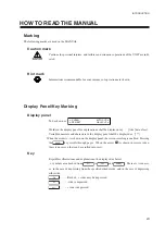
Страница 9: ...e numerals and characters in the display panel shall be displayed as When the arrow is shown on the display panel the screen scrolling is enabled Pressing the PAGE key scrolls through pages When the arrow is shown in reverse video there is no screen that can be scrolled into view Key Regardless illustrations and explanations the displayed as below symbols are attached from F1 to F4 and PAGE There ...

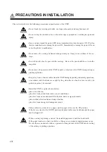
Страница 10: ...on Keep away from a 1 meter radius from the UNIT during its plotting and cutting operations or accidents such that hairs are caught by the grid roller or a hand or face is cut by the pattern paper may be occurred Install the UNIT at a place shown belows place out of the sun place free from a wind from such as an air conditioner place free from an environment filled by dirts dusts or cigarette smok...

Страница 11: ...onics Corp shall be called as the parallel connector parallel cable The Tools The tools is a general term for the pen sharp pen and cutter Tool conditions The conditions to use the tools shall be called as the tool conditions There are four conditions for the tool conditions Speed The rate to move the tools and sheet Press The force to push the tools onto a paper Acceleration The rate to increase ...

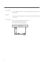
Страница 12: ... buffer Paper load A behavior to move the installed paper so as to detect the width and length shall be called as the paper load X axis and Y axis These axes show the coordinate system of the UNIT X axis is the direction of the sheet feeding Y axis is the direction of the carriage movement X axis Y axis Paper The UNIT ...

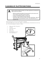
Страница 13: ...be taken to prevent inside of the UNIT from moisture When the cleaning solvent alcohol benzine is used care shall be taken not to exessively use The cleaning procedures for each section of the plotter are explained The cleaning shall be achieved at least once a month so as to maintain accuracy of the plotter and use it for a long time The sections requiring the cleaning are as follows 1 Surface an...

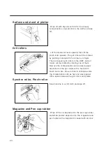
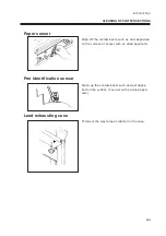
Страница 14: ...d all rollers will be rotated by rotating one of them Remove the contaminants such as waste paper deposited on the grit rollers with a hard tooth brush and a like Be sure then to eliminate enter ing contaminants such as hair and waste paper into a space between the grit rollers and platen Synchro roller Pinch roller Soak benzine in a soft cloth and wipe off Magazine and Pen cap rubber Wipe off the...

Страница 15: ...ited on the surface of sensor with an dried applicator Pen identification sensor Clean up the contaminants such as dust depos ited on the surface of sensor with an dried appli cator Lead exhausting case Throwout the waste lead collected in the case CLEANING OF PLOTTER SECTIONS ...

Страница 16: ...xiv ...

Страница 17: ...CHAPTER 1 SET UP 1 1 CHAPTER 1 SET UP This chapter covers all necessary precautions for the initial set up before start using unit This chap ter therefore must be read before practical use ...

Страница 18: ...NFIGURATION NAME AND FUNCTION 1 2 3 4 5 6 7 9 8 10 11 12 13 14 15 16 1 Front cover This prevents contact with the movable parts of the plotter during plotout 2 Platen This is the working table for the plotout ...

Страница 19: ...This is the portion to support the plotter main unit The casters equipped therewith allow the plotter to move easily 10Paper basket The basket catches the plot out pattern paper 11Roll shaft This is to set the roll paper 12Roll paper stopper This is to stop rotating of the roll paper when it is set 13AC inlet The power cable is connected 14Interface connector This is the serial interface connector...

Страница 20: ...the packing list If any missing is found please contact with our agent or branch office Main unit Main unit 1 Front cover M002066 1 Magazine M000924 1 Wastelead case M000641 1 Mechanical pen set OWP XP NS35 1 Respectively 1ea for 0 3 0 5mm with spare leads Water ball pen 40HP06 S 1 Black Zea Respectively 1ea forred blue and green Box for Accessory Part Name Part No Qty Illustration Remarks ...

Страница 21: ... at the time of delivery VM0306B VM304B 4N 200V Grounding adapter YM 19207 0 1 For 2P 3P conversion Instruction manual D200258 1 Packing list 1 T hexagonal wrench NO 9200 H6 150 1 For stand assembly Rubber cap M700107 4 For stand assembly Butterfly nut N4 1 type 4 For paper basket installation PACKING CHECK Part Name Part No Qty Illustration Remarks Box for Accessory ...

Страница 22: ...lar Ø4x25 4 For paper bascket installation Spacer M600525 4 For paper bascket installation Bolt CP8x25 2 For main unit installa tion Wing bolt M4 Type 1 x 10 4 For roll stays right left installation Warranty D900019 1 Part Name Part No Qty Illustration Remarks Box for Accessory ...

Страница 23: ...at front ways Right stand assembly M002145 1 Right hand looking at front ways Stand stay M002147 1 Paper basket assembly M002065 1 Roll paper PDW950x40m 70k 1 Flange for 2 inch M600186 2 3 inch roll holder M002316 1 assembly right Part Name Part No Qty Illustration Remarks Box for stand PACKING CHECK ...

Страница 24: ...1 8 3 inch roll holder M000815 1 assembly left Roll stay assembly M002310 right 1each M002311 left Handle assembly M000794 1 Part Name Part No Qty Illustration Remarks ...

Страница 25: ...ssy ASSEMBLY OF PLOTTER General Description Assemble the plotter in order as instructed below or you can not install all of the parts 1 Assemble the stands stand stay and main unit 2 Install the roll shaft assembly 3 Install the paper basket 4 Install the roll paper stopper assembly Roll stay assy ...

Страница 26: ...y part on the body The assembly work must be achieved in an open place with space of at least 3m x 4m 1 Insert the pin and bolt of the stand stay into the hole of the left stand with putting the pin side upward 2 Insert the pin and bolt of the other stand stay into the hole of the right stand Stand stay Pin Right stand Right stand Bolt ...

Страница 27: ...e packing box by two persons Hold the main unit at positions near its center portion If the positions at the both ends of the main unit are held it is possibility to put the hands between the main unit and stand 5 Put the main unit on the packing box once insert the bolts into the holes at the both side faces ASSEMBLY OF PLOTTER Caster 10mm ...

Страница 28: ... with the front face of the stands fot the enbedding 7 Insert the hexagonal wrench into the hole of the stand and finally tighten the bolt 8 Finally tighten the stand stay bolt once tightened temporarily Forward Cross sectional drawing of the stand Hexagonal wrench Hexagonal wrench ...

Страница 29: ...the stand comes at the nearly center portion of the above elongated hole Secure with four butterfly bolts Left hand 2ea Right hand 2ea Be sure to finely adjust the roll stays after placing a sheet of paper on the roll stays See page 2 8 1 1 Install the front cover Insert the right side pin into the hole of the main unit Rubber cap Front cover ASSEMBLY OF PLOTTER Elongated hole ...

Страница 30: ...nit and the corner of the case for the installation A magnet enables the waste lead case to be installed 1 4 Install the paper basket Position the longer arm so as to be located at the front side Sequentially insert the following parts in order into the screw protruded inside of the stand 1 Tube collar 2 Spacer 3 Hole of basket 4 Fasten with butterfly nut Pen Pin Waste lead case Spacer Tube collar...

Страница 31: ...oll paper stopper assembly onto the protrusion of the clamp arm located on the platen Install onto the electrical equipment cover with 2ea of the stopper screws Make sure that the roll paper stopper normally functions after placing a roll paper on the machine See page 2 6 Roll paper stopper assembly Stopper screw Clamp axis arm Protrusion ASSEMBLY OF PLOTTER ...

Страница 32: ...ir conditioner A place free from the air filled by dirts dusts or cigarette smoke A place without affection from a strong vibration A place free from strong electromagnetic source A place ensuring a space of at least 2000mm W x 1500mm D x 2000mm H 1 Release the stopper of the caster When the stopper of the caster 4ea are lifted the locks are released and the plotter becomes movable 2 Move the plot...

Страница 33: ...CHAPTER 1 SET UP 1 17 SET UP OF PLOTTER Lock 3 When the plotter is arrived at the place where it is set up secure it at the position with locking the stopper ...

Страница 34: ...o prepared as an optional component Please use the interface applicable to the specification of the host computer and application software The inter face connector is located at the back of the main unit RS 232C interface It is necessary to establish the condition communication condition such as the datatransfer rate for using this interface Establish the communication condition in accordance with...

Страница 35: ...moved cover shall be kept in storage with other attached accesso ries 3 As confirming the correct direction of the connector of the RS 232C cable insert into the RS 232C connector Secure the connection by tightening the screw 4 Make sure that the host computer power is turned OFF and insert the connector of the RS 232C cable into the RS 232C connector of the host computer Refer to the instruction ...

Страница 36: ... selected at ON position 2 Remove the dust cover of the parallel connector option to be embodied in the factory at the back of the plotter main unit The removed cover shall be kept in storage with other at tached accessories 3 As confirming the correct direction of the connector of the parallel cable insert into the parallel connector ...

Страница 37: ...spring 5 Make sure that the host computer power is turned OFF and insert the connector of the parallel cable into the parallel connector of the host computer Refer to the instruction manual of the host computer for the details CONNECTION OF CABLES Lock spring ...

Страница 38: ...power cable to a receptacle with the following specifications Domestic Overseas 100V Overseas 200 V Voltage AC100 120V 10 Voltage AC200 240V 10 Frequency 50 60Hz 1 Frequency 50 60Hz 1 Current 1 5A and over Current 0 75A and over 1 Connect the power cable to the power inlet of the plotter 2 Connect the power cable to a 3 pins power receptacle For the connec tion to a 2 pins receptacle install the g...

Страница 39: ...ng buffer is incorporated the display as shown left will be appeared 3 The carriage moves to the right end 4 When a magazine is loaded on the plotter the message shown in the illustration given at the left will ap pear on the display panel If you have replaced the cutter with a new one before turning the power ON press the F3 key In any case other than the above press the F4 key If no magazine is ...

Страница 40: ...se the set lever upward and the display will be ap peared Turning the Power OFF Do not turn OFF the power while receiving data or existing due out data If not a malfunction will be resulted in by turning ON the power at the next time 1 Put the power SW at the OFF posi tion The power indicating lamp will be lighted OFF as well as the dis play on the LCD will be faded out CLEAR AUTO CUT PEN SET HALF...

Страница 41: ...e menu and submenu When both sides have symbols either side may be pressed If one side has a symbol which shall be pressed END key The key shall be pressed for entering the set values ONLINE OFFLINE key The key shall be pressed to change over the offline mode and online mode When pressing the key under online mode the operation will halts Jog keys The key shall be used to move media and carriage a...

Страница 42: ...set and the paper load is executed the mode automatically changed over to the ONLINE mode READY mode This mode means the time for 5 seconds after the media setting and paper loading PAUSE mode A plot out operation is temporarily stopped CLEAR AUTO CUT PEN SET HALF CUT CLEAR AUTO CUT PEN SET HALF CUT ONLINE OFFLINE ON LINE ON LINE 1 20g 20cm 2 0G ONLINE OFFLINE REDY sec Power ON OFFLINE mode Data c...

Страница 43: ...AGE PAGE 1st page 2st page 3st page 4st page 5st page 6st page Menu List of Off line Mode There are menu consisting of six pages in the OFFLINE mode The pages can be changed by PAGE key as shown below There are four setting items in one page and pressing the function key causes setting each item or entering into the sub menu P 3 4 P 2 8 P 3 10 P 3 11 P 3 14 P 3 16 P 3 20 P 3 21 P 4 3 P 4 6 P 3 24 ...

Страница 44: ...the CAD is in compliance with the HP GL command this setting may be omitted in most cases Therefore closely read the instruction manual for the CAD so as to only carry out the setting to be required Sea page 3 24 Origin The position of origin of the plotter coordinates shall be established The se lection from the two choices shall be compatible with the type of command coordinates of the CAD If th...

Страница 45: ...ot a communication condition in general however this is involved in the communication condition for the UNIT There are three types of the setting method of communication conditions 1 Utilization of Existing Communication Conditions The following communication conditions of three patterns are stored in the UNIT If any pattern s be compatible with your CAD system the communication conditions may be ...

Страница 46: ...own the setting can be accomplished as receiving data from the host computer Since this method requires somewhat elapse time if the conditions are known it is recommended to set by means of the method 1 or 2 Refer to AUTOMATIC INTERPRETATION OF COMMUNICATION CONDITIONS See page 3 25 for the setting method Change over of Registration Number of Communication Condi tions 1 Be sure to be the OFFLINE m...

Страница 47: ... bit length stop bit length and parity check 1 Carry out the Steps 1 to 3 of Change of Registration No select the No to be changed 2 Select the CONDITION and the following display will be appeared 3 Select the values of BAUD DATA S BIT and PARITY The numbers will be changed whenever the key is pressed Display the objected value Change of the transfer speed F1 19200 9600 4800 2400 1200 600 300 EXTR...

Страница 48: ...n the display 4 Change the HANDSHAKE method The method will be changed when ever th key is pressed Display the objected method F1 XON XOFF ENQ ACK software hardware Should a setting a signal line be continued proceed with the Step 4 of the Block 3 in the next page 5 Enter the input values and returned to the 6th page of the menu F3 BAUD XXXX DATA X S BIT X PARITY X HANDSHAKE X ON X OFF CONTROL FIL...

Страница 49: ...r the values of CON TROL The values will be changed whenever the key is pressed Display the objected value Change of the value of ER F1 Normal Control Change of the value of RS F2 Normal Control Change of the value of CD F3 Normal Check 6 Enter the changed values and re turned to the 6th page of the menu Should a setting the EOF command and close timer proceed with the Step 3 of the Block 4 in the...

Страница 50: ...TION 3 Invoke the 2nd page of setting the conditions 4 Select the FILE CNTL and the following display will be appeared 5 Change the values of CLOSE TIME The values will be changed whenever the key is pressed Display the objected value F3 10sec 30sec 1min 3min OFF If the EOF COMMAND is set first further steps of proce dures will be increased Therefore the CLOSE TIMER should be changed first 6 Selec...

Страница 51: ... Proceed with the next page 9 Change over ON OFF of the ZT 0 NR and PG The ON OFF will be changed over whenever the key is pressed Display either one Change of the value of ZT 0 F1 OFF ON Change of the value of NR F2 OFF ON Change of the value of PG F3 OFF ON 10 Enter the changed values and re turned to the 6th page of the menu Now changes of the communication conditions have been completed SETTIN...

Страница 52: ...ed in this plotter shall be explained hereafter The setting shall be at the maximum value and below Sharp pen It is suitable for high speed plotting Places to be corrected may be easily erased with a eraser The operations such as detecting with or without lead lead feeding and supplying or exhausting lead are auto matically accomplished The surface condition of the media relates to the adher ing q...

Страница 53: ... is beated dropped or rubbed with hard and rough surface the line becomes narrower and wider When the plotting speed is extremely slow the ink jet may well be worse In addition a ball is used for the tip the line be comes blurred at start writing Ceramic ball point pen Option Since the pen point is protected with ceramic a uniform line width can be maintained from the start writing to end of the i...

Страница 54: ... the pen point In addition a ball is used for the tip the line be comes blurred at start writing When a roll of paper is used the maximum speed will be 60 cm s Cutter The cutter shall be used after attaching the cutter blade onto the holder Since the cutting blade edge is deviated from the center of the holder a value of offset shall be established for the compensation Use for a long period may re...

Страница 55: ... functions are executed the plotter will use it MOVEMENT OF ORIGIN P 3 12 3 POINT AXES COMPENSATION P 3 16 How to install Viewer Remove the pen cap rubber of the autocap or the viewer tip will be contaminated by the ink depositted on the pen cap rubber resulting in suffering from insufficient performance of the viewer When the viewer is taken out align the viewer type with the objected position on...

Страница 56: ...il based plastic pen Suitable for operations under intermediate plotting speed 40cm s Coloring condition is good Suitable for process color plinting and illustration Pressurized oil based ball pen Easy correction High speed plotting is possible 100cm s Sticking of ink is sometimes not fast at beginning Ceramic ball pen Since the pen point is ceramic a uniform line width can be maintained until end...

Страница 57: ... not be achieved No identification seal is stuck on the pens Accordingly the plotter can not interprete the type of pen When the automode is selected for the tool mode because only one type of tools conditions can be set if a pen of which plotting condition is different is used the plot out will not be pretty enough in some cases When several different types of pens are to be used apply the manual...

Страница 58: ...strong impact thereto It may cause dam ages Do not remove or contaminate the identification seal It will be resulted in default to identify for with or without the pen or type of the pen If con taminated wipe off with soft and clean cloth Use the lead specified by MIMAKI ENGINEERING CO LTD for the Me chanical pencil The Mechanical pencil consists of the following part ...

Страница 59: ...plied by the lead feeding system If the lead feeding operation can not supply the lead the Mechanical pencil will be returned to the magazine Under the automode another Mechanical pencil filled with the same lead diameter if any in the magazine is automatically takes the place and the plotting can be continued When all leads have been used under the automode or the lead in the assigned Mechanical ...

Страница 60: ...2 Replace the removed cap hold the Mechanical pencil vertically Knock the cap so as to extend the lead a little from the pen point The maximum quantities of leads filled in one time are as follows 0 2mm 120 leads 0 3mm 70 leads 0 4mm 45 leads 0 5mm 30 leads 3 After confirming the coming out the lead from the pen point lightly press on the table at the vertical position as knocking the cap so as to...

Страница 61: ...ged discrepancies such as malfunction of the inner barrel malfunction in lead extending by knocking and fail in lead charging discharging function are happened Remove the clogged lead in accordance with the following procedures 1 Disassemble the Mechanical pencil and remove the inner barrel 2 Insert the cleaning needle from the tip of the inner barrel and remove the lead 3 Remove the lead tank THE...

Страница 62: ...1 46 4 Press the lead tank by fingers then take out the lead Do not enter the cleaning needle into the chuck or it causes damage of the chuck portion ...

Страница 63: ...tion is frequently repeated Waste leads of 15mm long are exhausted into the waste lead case The Mechanical pencil is returned to the magazine and the message NO LEAD is displayed then the operation stops Since the service life is not suddenly expired check the chuck and inner barrel and purchase new pens for the replacement if necessary Check of service life of the Chuck 1 Extend the lead as much ...

Страница 64: ... If deterio rated wipe off lead dust with an applicator 2 Install the cleaned inner barrel on the Mechanical pencil and extend the lead as much as one knocking Push the inner barrel by finger so as to enter into the plunger as shown in the illustration 3 Lightly tap the Mechanical pencil body If the inner barrel comes down it shows the service life ex pires ...

Страница 65: ...existence of the cutter or type of the cutter If con taminated wipe off the dirty part with soft and clean cloth Do not shake the cutter It is very dangerous because it will cause the cutter blade comes off and injures a person The cutter blade is a consumable If the blade has become dull replace it with a new one The cutter consists of the following component parts THE TOOLS Holder Adjusting knob...

Страница 66: ... Cutter Blade The proper diustance of the blade extension shall be 0 3 0 5mm 1 Remove the holder from the cutter 2 Put the cutter blade into the nozzle with a pincette and push until bot toming 3 Remove the holder Holder ...

Страница 67: ...e blade can be changed Referring to the illustration left adjust the extent of the exten sion If you use the blade adjuster optional good the distance can be accurately adjusted The proper diustance of the blade extension shall be 0 3 0 5mm 5 Tighten and secure the lock nut THE TOOLS Adjusting knob Lock nut ...

Страница 68: ...r a Mechanical pencil will sometime cause scratching paper and the like There are the following two types in the ordinary paper Select a suitable one in accordamce with the purpose of use PD paper Among ordinary types of paper this is the most suitable for the plotting A little stretch property is involved and even if plotting speeds are variable visible line quality can be obtained PDW paper This...

Страница 69: ...epending on the ambient temperature and humidity Put the paper near the plotter for 30 minutes and over and expose in the atmosphere The roll paper will be sometime stretched immediately after unrolled Curling Do not use extremely curled paper or resulting in getting clogged For paper of which curled level is low set the paper so that the curled portion comes inside of the platen so as to prevent ...

Страница 70: ...1 54 ...

Страница 71: ... CHAPTER 2 BASIC OPERATION This chapter covers the basic operation to plot out the pattern paper The instructions are prepared sequentially in accordance with the steps of the works therefore read the instruction from the beginning ...

Страница 72: ...age 2 10 Tool up Speed Setting See page 2 14 Dotted Line Cut Setting See page 2 15 Sorting Settin See page 2 16 Autocut Setting See page 2 18 3 Set of Paper and the Tools onto Plotter Installation of Magazine See page 2 20 Paper Setting Set of roll paper See page 2 25 Set of leaf paper See page 2 29 Accomplish the self diagno sis function so as to confirm the tools condition and no failure may be ...

Страница 73: ...ng the work Preparation of Paper Use of Roll Paper Refer to Load of Roll Paper See page2 4 for the roll paper and install on the main unit Use of Leaf Paper It is necessary to adapt the paper unpacked and removed from the packing box to the ambient temperature and humiditiy in the room Put the paper on a flat table and leave in the atmosphere for 30 minutes and over Setting the leaf paper onto the...

Страница 74: ...ly 1 Shut the paper bascket at the rear side 2 Make sure that the paper set lever is at the UP position 3 Sequentially load the roll holder right roll paper and roll holder left in order onto the roll shaft Roll paper Roll holder right Roll holder left Roll shaft ...

Страница 75: ...arily tighten the both left and right set screws of the roll holders 5 Knock the roll holder against the stopper of roll shaft 6 Tighten fast the both left and right set screws of the roll holders PREPARATION OF PAPER AND THE TOOLS Set screw Stopper Set screw ...

Страница 76: ...ew is mounted is positioned near the keyboard Make sure the direction of the roll paper Load the roll paper as the CORRECT side of the illustration as shown left 8 Secure the roll paper with the sheet set lever raised At this time check to be sure that the wing of the wing setscrew will not turn any more once it comes in contact with the stopper Rear side Set screw Front side Wing set screw ...

Страница 77: ...d 3 The carriage moves to the right end 4 When a magazine is loaded on the plotter the message shown in the illustration given at the left will ap pear on the display panel If you have replaced the cutter with a new one before turning the power ON press the F3 key In any case other than the above press the F4 key If no magazine is loaded on the plotter proceed to Step 6 5 Initialize the magazine 6...

Страница 78: ...itions for the set tools are assigned for the plot out The types to be interpreted are the following six kinds Mechanical pencil 0 5mm Mechanical pencil 0 4mm 0ption Mechanical pencil 0 3mm Mechanical pencil 0 2mm 0ption Viewer 0ption Cutter Others pens other than Mechanical pencils and cutter The tools other than the Mechanical pencils and cutter are all identified as Others If an ink pen and bal...

Страница 79: ...tions receiving from the host computer use the condition with the manual mode 1 The first page of the menu is dis played 2 Select PEN SET and the following display will be appeared 3 Select MODE and the mode will be changed over whenever depressing the AUTO MANUAL key Select the applicable mode 4 Regifter the mode and the display will be returned to the first page of the menu F3 SAVE No 1 ASSIGN M...

Страница 80: ...e is drawn along with the direction of 45 is shown The larger rate hear the shorter time of the plot out Press The tool force of the pen and cutting force are shown Establish the suitable value according to the type and thickness of the paper to be used Increase this value if uncut paper is remained with use of a cutter or a ball pen do not draw clearly Offset Since the blade edge is shift from th...

Страница 81: ...ols conditions are registered Three different patterns of tool conditions can be registered for this machine Press g Speed cm s Acceleration G Pencil 0 5 350 120 5 7 Pencil 0 4 300 120 5 7 Pencil 0 3 260 120 5 7 Pencil 0 2 170 120 5 7 Others 20 20 2 0 Initial settings of pen pencil parameters common to three patterns Setting Method under Manual Mode Under the manual mode the conditions shall be se...

Страница 82: ...licable No 6 Change the values of ACC SPD and FORCE The value is changed whenever the key is depressed Display the objected value F2 ACCELERATION 0 3 1 0 2 0 3 0 4 0 5 7 F3 SPEED 2 5 85 5 step 120cm s The maximum speed is 60 cm s when a roll paper is used F4 FORCE 15 20 450g 10 step When other pen No is to be continuously established re turn to the Step 5 above then repeat the operation thereaf te...

Страница 83: ...and OFSET The value is changed whenever the key is depressed Display the objected value F1 SPEED 2 5 85 5 step 120cm s The maximum speed is 60 cm s when a roll paper is used F2 FORCE 15 20 450g 10 step F3 ACCELERATION 0 3 1 0 2 0 3 0 4 0 5 7G F4 OFSET 0 00 2 50mm 0 05 step 6 When all establishments have com pleted accomplish the registration The display returns to the first page of the menu PAGE C...

Страница 84: ...eed and acceleration of the specified value The display will be changed whenever the key is depressed Display the objected mode F3 UP SPEED 2 5 85 5 step 120cm s F4 ACCELERATION 0 3 1 0 2 0 3 0 4 0 5 7 G 6 Accomplish the registration The display will be returned to the firs page of the menu TOOL UP SPEED SETTING The moving speeds of the carriage and paper at tool up are establisyed Command Descrip...

Страница 85: ... CUT is set to the ON state a pressure command ZF transmitted from the host computer will be ignored Establish adequate settings in consideration of the CAD software specifications use environment type of paper data and tool conditions 1 The first page of the menu will be displayed under the off line mode 2 Select HALF CUT and the following display will be apperared 3 Change the items to be establ...

Страница 86: ...e UNIT the following two types of sorting are incorporated Pen Sorting The received data are grouped by the pen No The plotting is achieved from low pen No in order Without setting of pen sorting With setting of pen sorting Vector Sorting A plotting is continued upon moving from the plotted line segment to the nearest line segment Pen change 1 2 Pen change 2 1 Pen change 1 2 Plotting of Pen No 1 P...

Страница 87: ...esulted in To output data on cutting and plotting specify the OFF VS or VL If the P or P VS is specified plotting will be performed on the part that is cut This will cause the pen tip to catch the cut part resulting in paper jam ming 1 Display the fourth page of the menu 2 Change the SRT The display is changed whenever the key is de pressed Select the applicable value The value will be automatical...

Страница 88: ...e finally cannot cut off the paper with a 450 g pressure it will give a message to prompt for cut ter replacement In this case be sure to replace the cut ter blade with a new one When a magazine is loaded on the machine the machine will give a message asking whether the cutter blade has been re placed If YES meaning that the cutter blade has been re placed with a new one is selected the cutter pre...

Страница 89: ...key is depressed When OFF is selected herein proceed with the Step 5 F1 CUT MODE CUT WAIT CUT PLOT OFF 4 Change the value of FORCE The value will be changed whenever the key is depressed Display the appli cable value F3 FORCE 50 450g 5 Accomplish the registration The display will be returned to the first page of the menu PAGE CLEAR AUTO CUT PEN SET HALF CUT F2 CUT MODE XXXXXXXX FORCE XXXg CUT OFF ...

Страница 90: ...Eight tools can be loaded on the magazine The specialized pen cap rubber to prevent the pen point from dry off is provided in the magazine auto cap There are each four caps for ink pens and ball pens respectively Be sure to use the pen cap for ink pens for the ink pens and ceramic pens For other tools both types pen caps are usable These pen cap rubber can be removed and installed INSTALLATION OF ...

Страница 91: ...es to the front 2 Hold the pen by your left hand install the collar of the tool horizontally between the upper and lower pawls of th magazine 3 When the thumb of your right hand is released the pen point gets into the auto cap For the pen cap rubber there are two types i e for the ink pen and ball pen Select and replace if necessary the proper rubber depending on the installed pen See page Structu...

Страница 92: ...wer ON 1 Make sure that the UNIT stop operat ing Holding the magazine shaft steadily insert into the magazine holder of the plotter 2 Lightly turn the magazine until bot toming A click of a latch comes out and the magazine is rotated When a magazine is loaded on the machine the message CHANGE CUTTER BLADE will appear on the display Select YES or NO YES The pressures for the auto cut and pattern cu...

Страница 93: ...en number in which no pen is installed the ma chine will not fetch the pen Instead the machine will continue plotting using the pen that is currently installed in the carriage Indication of pen numbers DATA No A 1 2 3 4 5 6 7 8 PEN No 1 1 2 4 5 5 7 8 The pen number contained in data shown above corresponds to the magazine pen numbers as shown in the table below Pen number in data 1 2 3 4 5 6 7 8 P...

Страница 94: ...splay the first page of the menu 2 Select PEN SET and the following display appeares Check to be sure that the mode is set to the MANUAL If the AUTO mode is selected press the F3 key to change over the mode to the MANUAL 3 Select DATA No and the following display appeares Select the DATA No using the or key The selected number will be shown in reverse video Using the or key establish the PEN No co...

Страница 95: ...acting with the gdit roller under plotting for a long time Load the paper after all settings have been accomplished Both roll paper and leaf paper are usable in the UNIT Roll Paper Setting 1 Make sure that the paper set lever is at the UP position 2 Load the paper between the pinch roller and grit roller at the back of the main unit Grit roller Pinch roller ...

Страница 96: ... and pull out and stretch the paper from the roll by both hands When the extent of pull out of the media is too short pull out the media by lifting the roll paper stopper upward 5 Make sure that the paper adsorbs without deflection then lower the paper set lever at DOWN position as holding down the roll paper in place by hand 6 The display as shown left will be appeared The display would not be ap...

Страница 97: ... and the mode becomes under the online mode When the paper is set the UNIT automatically becomes under the online mode If you want to change the tools conditions communication condi tion and etc after setting the paper select the offline mode or pause mode If you want to move the origin refer to Chapter 3 MOVEMENT OF ORIGIN P 3 12 When the online mode is selected in some cases the plotter may star...

Страница 98: ...and behind the plotter 2 For the case illustrated in Fig A shift the roll stay located near the operation panel toward the back of plotter or shift the roll stay assy located on the opposite side toward the front of plotter or respectively shift both roll stays to the aforemen tioned directions 3 For the case illustrated in Fig B shift the roll stay located near the operation panel toward the fron...

Страница 99: ...ng with the inner end of the right gdit roller on the platen 2 Move the right pinch roller to the clicked point at the right end The right pinch roller shall be positioned at the clicked point where is rightward from the right gdit roller Position of right side pinch roller PAPER SETTING Leaf paper For roll paper set grit roller For leaf paper set grit roller ...

Страница 100: ...THICK 90g m2 and over F2 CUT THIN Less than 90g m2 The display as shown left will be appeared the carriage moves left and right and the paper moves back and forth 6 When the movement stops the display as shown left will be ap peared The part will be changed from 5 to 1 Depressing during displaying this picture causes to move into the offline mode 7 The mode becomes under the online mode C U T T H ...

Страница 101: ...age PAPER SETTING P 2 25 5 Is the area where the paper moves free from any obstacle See page PRECAUTION IN INSTALLATION P viii 6 Is the plotter under the online mode The UNIT will become the online mode whenever the paper is set When the offline mode is selected after setting the paper depress the so as to obtain the online mode Before practically plotting out A self diagnosis functions are incorp...

Страница 102: ...ale has been set the scale is displayed here If the scale is 100 there is no display Refer to PLOTTING SCALE SETTING P 3 14 While the mirror setting is ON R is displayed here If it is OFF there is no display Refer to MIRROR SETTING P 3 11 When data exceed the operating range is displayed here There is no display in gen eral When this display is appeared the data out of the plotting range can not b...

Страница 103: ... mode is obtained and movement of the plotter stops The tools conditions may be changed only parameter change during the pause mode The method is differed from tool mode Refer to the applicable page and change the condition Under automode Chapter 3 CHANGE OF THE TOOLS CONDITIONS Step 2 on in P 3 6 Under manual mode this chapter Setting Method under Manual Mode Step 2 on in P 2 11 3 Depress the key...

Страница 104: ...display is appearted the plotter operation would not be stopped 4 After a little while the display will be changed to as follow There is a few times lapse till complete stop of the plotter The length of the time lapse is differed de pending on the data 5 When the plotter completely stops the CLEAR function can be ex ecuted to clear the data Depress the key and the following display will be appeare...

Страница 105: ...per set lever at the UP position without fail The roll paper just leave on the roll holder for next opera tion 2 Remove the magazine from the UNIT Hold the magazine shaft and steadily lift up 3 Remove the tools from the removed magazine If the pen is left in the magazine it may well be dried off and become impossible to write Therefore firmly put a cap and store it in such as accessory box The mec...

Страница 106: ...magazine around 90 and leave your hand The magazine rotates after clicked and stops at the home position The magazine may be removed from the UNIT however it is recommended to install on the main unit so as to prevent damage by such as dropping on the floor 6 Turn the power of the plotter OFF Bring the power switch under the control panel down toward the O side ...

Страница 107: ...CHAPTER 2 BASIC OPERATION 2 37 7 Shut the paper basket Now all works have completed OPERATION END ...

Страница 108: ...2 38 ...

Страница 109: ...CHAPTER 3 APPLIED FUNCTIONS 3 1 CHAPTER 3 APPLIED FUNCTIONS This chapter covers the applied functions which make you much convenient operation ...

Страница 110: ...rror Setting P 3 11 his is a function to plot out received data by reverting the X axial center line on the axis Application Setting Change of the Tools Conditions P 3 6 The tools conditions in the registration Nos 1 2 and 3 will be changed If there is no suitable tool condition in the three patterns of the initial values the change will be achieved here Change of Origin P 3 10 An origin of coordi...

Страница 111: ...per type by every time or selecting default paper type will be changed over Resolution Setting P 3 24 The resolution of the plotter will be set Plotting List to be set up conditions P 3 23 The data of all settings of the UNIT will be plotted Automatic Interpretation of Communication Conditions P 3 25 A function to set communication conditions as transmitting data from the CAD to be used by the use...

Страница 112: ... be executed The display returns to the first page of the menu Execute the data clear after the plotter movement completely stops If the data clear is executed during movement the data remains in the buffer This status may well cause a malfunction or erroneous operation when the next online mode is selected If the plotter side is unavoidably stopped in advance execute the following procedures 1 St...

Страница 113: ...the paper cut off has been ended the page will be returned to the first page of the offline mode Cutting before Paper Load 1 Pull out the head of the roll paper on the platen so as to locate the position to be cut off on the synchro roller 2 Select AUTOCUT With holding the cramp lever at risen position 3 Follow the display on the panel hereafter 4 When the paper cut off has been ended execute the ...

Страница 114: ... paper is used CHANGE OF THE TOOLS CONDITIONS Establish operating conditions for plotter pens of REGISTER Nos 1 2 and 3 according to the type of paper and tool to be used The contents and values of the setting are as follows Refer to Chapter 1 MERITS OF THE TOOLS P 1 36 for the tools conditions compatible with the tools and or paper This setting is stored even if the power is turned OFF 1 Under th...

Страница 115: ...ange the values of ACC SPD and FORCE The value will be changed whenever the key is de pressed Display the applicable vslue F2 ACCELERATION Refer to the condition list in the previous page F3 SPEED Refer to the condition list in the previous page F4 FORCE Refer to the condition list in the previous page Return to Step 5 and repeat the operation to continue to change the other tools 8 When all setti...

Страница 116: ...ta 3 that is firstly received will be the object to be copied Data 2 and 3 can not be copied Send the data once again for the copy Along with EOF command for each page or send data one by one page for copying without EOF command EOF command OFF Since there is no pause in the receiv ing buffer all data in the receiving buffer will be copied on the same paper When the command of the CUT in the subme...

Страница 117: ...d F3 1 99 sheets When leaf paper is set this command becomes ineffec tive 7 Select CUT Every depressing the key causes the change over If it is desired to cut at the pause of the data turn ON F4 ON OFF When leaf paper is set this command becomes ineffec tive 8 Execute the copy If discontinuation of the copy is desired depress so as to obtain the pause mode then execute the DATA CLEAR P 3 4 instruc...

Страница 118: ... herein is stored in the memory even though the power is turned OFF Origin at the center 1 Display the second page of the menu under the offline mode 2 Select ORG CENTER and COR NER are changed over by depress ing the key Select the applicable origin 3 The origin will be automatically registered Front side Origin Origin at corner PAGE ORG CENTER COPY MIRROR OFF ORG MOV ORG CORNER COPY MIRROR OFF O...

Страница 119: ...the mirror This command will be stored in the memory even though the power is turned OFF Plotter X axis center line Original data 1 The offline mode will cause to display the second page of the menu 2 Select ON OFF of the mirror The display will be changed whenever the key is depressed and the selection will be automatically registered F3 ON OFF PAGE ORG CENTER COPY MIRROR OFF ORG MOV ...

Страница 120: ...he paper Refer to Chapter 2 PAPER SET TING P 2 25 2 Select the offline mode Execute DATA CLEAR P 3 4 in this chapter 3 Move the head to the applicable position of origin by using JOG key 4 Set the origin After a little while page of the offline will be displayed The origin set as this method will be initialized when a paper load is executed Origin at the center Effective plotting area Origin after...

Страница 121: ...ove speed at this time may be changed Every depressing F2 causes changes of speeds There are three types of speeds as follows L slow M intermediate H fast 4 Set the origin 5 When moved to the destination store in the memory by depressing the key The origin set as this method will be effective even after a paper loading or turning the power ON OFF For the initialization Execute ORIGIN INITIALIZE MO...

Страница 122: ...er to Chapter 6 TABLE OF SCALES P 6 12 for the scale factor of the reduction and enlarge ment 1 The third page of the menu will be displayed under the offline mode 2 Select SCALE 3 Change the RATE F1 To be 100 F3 To reduce down to 10 F4 To enlarge up to 1000 4 Register the scale X X Y X Y Y Y X SCALE AUTO FEED COMPEN DIST CMP PAGE F1 INITIAL RATE 100 REDUCTION ENLARGE END SCALE AUTO FEED COMPEN DI...

Страница 123: ...1 The third page of the menu will be displayed under the offline mode 2 Select AUTO FEED 3 Change the FEED LNG and FEED F1 3 0 0 0m 0 5 step F1 3 0 9 5m 0 5 step F3 AT PAPER LOAD AT PLOT START 4 Register the auto feed There is a function to detect a slippage before the paper is slipped off from the pinch roller Input the value of SKEW in the process of SYS TEM SETTING P 3 27 in this chapter The sl...

Страница 124: ...alues for the lean of the paper distance and perpendicularity This setting shall be accomplished after the paper setting When the next paper is set this setting will be released Setting Procedure a Set the Points 1 2 and 3 in the left illustration by the JOG key b Input the X axis Point 2 Point 3 and Y axis Point 1 Point 2 in length which have been actully measured 1 Set the pen or viewer on the m...

Страница 125: ...ster the Point 3 and the follow ing display will be appeared and the carriage moves to the right lower corner of the paper The distances of the Point 2 Point 3 and Point 1 Point 2 measured by the plotter will be displayed respectivly on the X AXIS and Y AXIS 12 Change the values of X AXIS and Y AXIS to the values actually mea sured F1 The value of the X axis will be changed by the unit of 0 1mm F3...

Страница 126: ...eparately available viewer 2 Set the paper Refer to Chapter 2 PAPER SET TING P 2 25 3 Select the offline mode Execute DATA CLEAR in this chapter P 3 4 4 The third page of the menu will be displayed under the offline mode 5 Select LENGTH and the following display will be appeared 6 Set the size of plotting frame rectan gular of the X axis Assign the size corresponding to the set paper The value wil...

Страница 127: ... for compensation s sake will be excluded from the objects to be compensated Check the compensation under the online mode 8 Input the length actually measured F1 Change of value of XR F3 Change of value of XL F4 Change of value of Y 9 Accomplish the registration The display will be returned to the third page of the menu END SCALE AUTO FEED COMPEN PIST CMP XR XL Y Origin of compensation Main unit ...

Страница 128: ...c Short peep about 0 5 sec Long peep about 2 sec BUZZER SETTING The setting is related to use the buzzer or not for occurrence of an error or a malfunction There are the following buzzers in the UNIT This setting will be stored regardless the power ON OFF 1 The fourth page of the menu will be displayed 2 Change over the BUZZER ON OFF Every depressing the key causes the change over and the status w...

Страница 129: ... NAME SETTING The values corresponding to request for response of equipment code from CAD shall be established The follow ing 5 types of equipment are subjected to the selection This setting will be stored regardless the power ON OFF 1 The fourth page of the menu will be displayed 2 Select the applicable equipment Every depressing the key causes the change of equipment type and auto matic registra...

Страница 130: ...r type is fixed When the paper type is fixed the details of the paper shall be also set This setting is stored regardless the power ON OFF 1 The fourth page of the menu will be displayed 2 Select PAPER and the following display will be appeared 3 Select CHOICE and KIND F1 AT LOADING BY DEFAULT F3 ROLL LEAF THICK LEAF THIN LEAF THICK 90 kg base or more LEAF THIN Smaller than 90 kg base 4 Register a...

Страница 131: ...e No 1 then install the magazine on the UNIT Refer to Chapter 2 Preparation of the Tools P 2 21 2 Set the paper Refer to Chapter 2 PAPER SET TING P 2 25 3 Select the offline mode Execute Chapter 3 DATA CLEAR P 3 4 4 Display the fifth page of the menu 5 Select PRM LIST and the following display is appeared 6 Select PLOT START and the fol lowing display is appeared and the plotting will be started 7...

Страница 132: ...his setting is stored regardless the power ON OFF If this setting is incorrect the data will be enlarged or reduced when plotted out 1 Display the sixth page of the menu 2 Change the value of GDP The value will be changed whenever the key is depressed and automatically registered F1 0 025 0 05 0 01 PAGE GDP 0 025 I F SET AUTO I F CNTRL ...

Страница 133: ...can not be obtained because it is to interpretate the possibility of hard wiring When the communication conditions of the RS 232C of your CAD are unknown the conditions may be automati cally interpreted as receiving the data and registered into the assigned Nos 1 2 and 3 However since the received data would not be plotted it is not necessary to load the paper 1 Connect the UNIT and host computer ...

Страница 134: ...communication condition of the CAD and set in accordance with Chapter 1 SETTING OF THE COMMUNICATION CONDITIONS P 1 29 8 When the interpretation has been properly ended select the No to which the interpretation result com munication conditions is registered The number will be changed when ever the key is depressed Select the applicable No F3 1 2 3 9 Register the interpretation result into the No a...

Страница 135: ...ize when MGL II command IN is received VIBRATION 0 5 times Number of times to try cut again when autocut is not executed is assigned JOG SPD 0 85cm s Speed at JOG key move is assigned SL CUT 0 2 5 10 Slant cutting amount setting for auto cut shift JIS ENABLE DISABLE Shift JIS setting The underlined values are factory designated settings at the time of delivery SYSTEM SETTING The following settings...

Страница 136: ... third page 7 Select the items in the third page Select by F1 register by END Select by F1 register by END 8 End the system setting The display will be returned to the sixth page of the menu F2 NR to PG NO F3 PAPER END OFFSET 25 mm F4 SKEW CHECK 5mm PAGE IN CMD VIBRATION JOG SPD F1 PEN INIT BY IN CMD YES F3 VIBRATION RETRY COUNT 3 F4 cm s 0 DEFAULT JOG SPEED END GDP XXXXX I F SET AUTO I F CONFIG F...

Страница 137: ...CHAPTER 4 SELF DIAGNOSIS FUNCTION 4 1 CHAPTER 4 SELF DIAGNOSIS FUNC TION This chapter covers the functions to plot various setting of the plotter as well as to investigate abnormal states of the plotter ...

Страница 138: ...the cutting quality Square Cut P 4 4 A pattern is cut square so as to verify the cutter tooling condition Dump Test P 4 5 Received data are plotted with the ASCII data Status Display of Signal Conductor P 4 6 The status of the RS 232C signal conductor is changed over so as to display on the display panel Plotting of Demonstration Pattern P 4 7 A pattern is plotted so as to verify the plotting qual...

Страница 139: ...ing posi tion move the position of origin Execute Chapter 3 MOVE MENT OF ORIGIN P 3 12 4 Display the fifth page of the menu 5 Select SELF TEST and the follow ing display will be appeared 6 Select SMPL CUT and the follow ing display will be appeared and the cut will be started 7 The cut is ended and returned to the first page of the menu 280mm 75mm SAMPLE CUT Cut the sample shown below so as to ver...

Страница 140: ...he posi tion of origin 4 Display the fifth page of the menu 5 Select SELF TEST and the follow ing display will be appeared 6 Select SQR CUT and the following display will be appeared and the cut will be started 7 The cut is ended and returned to the first page of the menu SQUARE CUT A square pattern is cut so as to verify the cutter tooling condition and set of the half cut Set the cutter on the m...

Страница 141: ... and leaf paper or roll paper of A2 and over 1 Set the pen in the magazine No 1 then install onto the main unit Refer to Chapter 2 Preparation of the Tools P 2 21 2 Set the paper Refer to Chapter 2 PAPER SET TING P 2 25 3 Select the offline mode Execute Chapter 3 DATA CLEAR P 3 4 4 Display the fifth page of the menu 5 Select DUMP and the following display will be appeared 6 Transmit the data from ...

Страница 142: ...power is turned OFF Under the line monitor mode when an error is detected the error mes sage will not be displayed However if the buzzer is turned ON the buzzer alarms the error Chapter 3 BUZZER SETTING P 3 20 1 Under the offline mode the fifth page of the menu will be displayed 2 Select ON OFF of LINE MONI TOR The ON OFF will be changed over whenever the key is pressed F3 ON OFF 3 Execute the onl...

Страница 143: ...o 8 If the cutter is installed it will be ignored The sample of the patterns areshown in P 4 9 Demo pattern 2 This is a pattern to evaluate the performance When you execute this pat tern set pens or mechanical pencils in the magazine Nos 1 to 4 The sample of the patterns are shown in P 4 10 1 Set the pen in the magazine then install onto the main unit Refer to Chapter 2 Preparation of the Tools P ...

Страница 144: ...e plotting will be started When the Demo pattern No 2 is plotted select 2 and the following display will be appeared and the plotting will be started 7 The plotting is ended and returned to the first page of the menu F2 TEST 2 X XXXg XXXcm X XG CLEAR AUTO CUT PEN SET HALF CUT F1 TEST 1 X XXXg XXXcm X XG ...

Страница 145: ...CHAPTER 4 SELF DIAGNOSIS FUNCTION 4 9 DEMONSTRATION PATTERN 1 2 Demonstration Pattern 1 ...

Страница 146: ...4 10 Demonstration Pattern 2 ...

Страница 147: ...CHAPTER 5 TROUBLE SHOOTING AND POSSIBLE REMEDY 5 1 CHAPTER 5 TROUBLE SHOOTING AND POSSIBLE REMEDY This chapter covers the methods to solve troubles ...

Страница 148: ...patible with the power SPEC Connect to the receptacle agreed with the power SPEC See page 1 22 Yes No Is the paper properly secured with the right and left pinch rollers Secure the paper at the correct position For roll paper See page 2 25 For leaf paper See page 2 29 Are the pinch rollers properly placed on the grid roller Move the pinch rollers until they are properly placed on the grid roller F...

Страница 149: ...fe of the mechanical pencils See page 1 46 1 47 Properly set the origin See page 3 10 Is the origin setting agreed with CAD data No Under mechanical pencils plotting knocking happens fre quently A cut plot is slipped off Yes No The media runs off from the pinch roller The plot out has been achieved for a long time and the media stron contact with the floor or the like Reduce the speed of the tools...

Страница 150: ...ple and folded mark See page 1 53 Do you use paper without exessive curl crumple and folded mark Is the plunger of mechanical pen cils securely installed Is the magazine properly set on the plotter Is the tool of pen No assigned by the CAD set Securely install the plunger to end plug See page 1 42 Properly set See page 2 22 Set the pen in the magazine No same as the pen No assigned by the CAD See ...

Страница 151: ...te Data Clear P 3 4 Is the spool function set at the CAD side When the spool function is set at the CAD side data received by the plotter may be discontinued It s the normal state and no problem Is the magazine that Mimaki sup plies use Is the tool operation mode the manual mode Execute Data Clear after CAD data transmit ends P 3 4 If there s no mark on the LCD the data from CAD is discontinued In...

Страница 152: ...ly assembled Are the Right and Left roll stays installed at the proper positions Correct the lean of roll paper See page 2 25 Align the front faces of the main unit and stand for the assembly P 1 12 Install the roll stays in such way that the screw hole of the stand omes at the almost center of the elongated hole of the roll stay P 1 13 Although a media is set the operation does not start Is the m...

Страница 153: ...nd for the dotted line cut mode transmitted from CAD Check to be sure that dotted line cut mode is ON and increase the re sidual part length See page 2 15 Change parameters established on CAD properly Paper is caught at the auto cut portion resulting in paper jam ming Does paper jamming arise in any case other than the time immedi ately after auto cut Increase the slant cutting amount See page 3 2...

Страница 154: ... CHANGE OVER OF ORIGIN P 3 10 select the proper position of origin Error in scaling Refer to Chapter 3 PLOTTING SCALE SETTING P 3 14 and change the scale value Autocut disables the Paper to cut Low cutting pressure Refer to AUTOCUT SETTING P 2 18 and set the proper value of press force Increase the auto cut pressure in increments of 10 g to establish a proper value Autocut does not cut the Paper D...

Страница 155: ...he paper jammed from the machine 4 Remove the paper jammed from the machine If a piece of paper has entered the hole in grid roller or in synchro roller also remove it 5 Turn ON the power switch Check to be sure that the machine normally conducts initialization 6 Re load the paper For a roll paper the top end of the paper may have bent or crooked Correct the paper following the steps of procedure ...

Страница 156: ...R I G I N S E N S E R R O R DISPLAY OF ERROR MESSAGE Methods to cope with trouble when an error message is displayed on the LCD There are two types of troubles as shown below A trouble that the plotter operation stops A trouble that the operation can be continued Troubles with Stoppage of Plotter Operation When the following error messages are displayed operation of the plotter will be stopped Tur...

Страница 157: ...iameter mechani cal pencil on the magazine Set the mechanical pencil of which pen No is the same as that of the mechani cal pencil which have been used Close the front cover Synchro roller and platen cover have been soiled on the surface 1 or 2 exceeds 45 and above Polygonal plotting hatching can not be achieved Short of memory Clean up the surfaces of synchro roller and platen P xii Set wirhin 45...

Страница 158: ...25 Contact to the MIMAKI distributor a Install the magazine attaching the pen b Turn the power OFF then turn ON again The pen is automatically returned to the magazine then recovery operation will be carried out Operate in accordance with the instruc tion in the LCD Provided that terminate the operation by pressing END if the plotter dis ables the pen to return a Pull out the magazine if the LH di...

Страница 159: ...on the plotter A command unacceptable for the plotter was received Properly establish the GL command A noise conducts into the commu nication circuit Do not use unacceptable commands The rolled media was skewed Use the interface cable specified by this MIMAKI The function was executed without setting the media Properly set the rolled media P 2 25 PENCIL ERROR CAN T STORE PEN C A N N O T E X E C U ...

Страница 160: ...d magazine No under auto manual mode Make sure that a DCD line is incorpo rated in the interface cable Confirm the specification of the host computer Execute dumping then confirm the data P4 5 a Refill the lead b When the lead remains disassemble the mechanical pencil and clean up the sliding portions of the inner barrel and mouth ring P 1 45 a Refill the lead b When the lead remains disassemble t...

Страница 161: ...DIX This chapter covers the explanations for the merit of the pens to be used maintenance of the UNIT specification of the UNIT and so forth In addition appropriate forms Inquiry Sheet and Optional Purchase Order Sheet and etc are involved ...

Страница 162: ...trical plot out inversed on the X axis center line is set 8 MOVE ORIG An origin is moved to an arbitrry position Dis tance apart from the referenced origin 9 SCALE The scale for plotting paticular to this plotter is set Differed from the scaling of the CAD side 10 AUTO FEED Establish length and timing of feeding at the time of paper loading 11 3 PT AXES When the existing reference line on the medi...

Страница 163: ...on Demo 2 The pattern to evaluate the perfor mance Sample cut For verification of the cutting quality Square For verification of the tools condi tions of the cutter and dotted line cutting 18 SET LIST The setting list is plotted out 19 MONITOR It is selected whether the RS 232C signal line status is displayed in real time or not 20 DUMP The received data are changed over to ASCII dump size mode 21...

Страница 164: ...ep 120cm s 0 3 1 0 4 0 1 step 5 7G OFF ON 0 15 20 80g 10 step 1 0 2 0 4 0mm 10 step 5 0mm 10 30 150mm 10 step CENTER CORNER Conduct copy 1 99 sheets ON OFF ON OFF Initialization of origin L M H Save Make 100 10 1000 1 step 10 1000 1 step 0 0 3 0 9 5m 0 5 step AT PAPER LOAD AT PLOT START Initialize the fundamental origin L M H Basic position 1 2 3 Drawing frame to measure the actual sizes 250 5000m...

Страница 165: ...uct the Demo pattern 2 drawing Conduct Sample cut Conduct Square cut test Plot out the setting list ON OFF Switch the mode to ASCII dump mode 0 01 0 025 0 05 1 2 3 Setting communication conditions Conduct the self diagnose FULL Yx1 4 1 0 3 0 5 0mm 1 step NO YES 0 25 125mm 1 step OFF 5 15mm 0 5 step YES NO 0 3 5 0 85cm s 0 2 5 10 ENABLE DISABLE PLOT 1 PLOT 2 SMPL CUT SQR CUT SAVE No CONDITION JUDGM...

Страница 166: ...n case of external setting Electrical Properties Connector Pin Arrangement Polarity Property A Property B Voltage Polarity Binary Notation 0 1 Control Signal ON OFF Status Display Space Mark P i n Signal Name N a m e Direction of signal 1 FG AA Protective ground 2 SD BA Tranmitting data 3 RD BB Receiving data 4 RS CA Transmit request 5 CS CB Transmit enable 6 DR CC Data set ready 7 SG AB Signal gr...

Страница 167: ...8 5V High fix 7 DATA6 19 30 GND 8 DATA7 32 ERROR High fix CENTRONICS INTERFACE SPECIFICATION The specification relates to 8bit parallel interface in conformity with Centronics Inc Connector Centronics connector 36 pins Pin Assignment Electrical Properties STB DATA BUSY ACK 1µs and above 3 5µs and above 3 5µs and above The UNIT side Host computer side Input output timing ...

Страница 168: ...utters tool type automatically recognized Maximum Lead quantity per 0 2mm 120ea Option mechanical pen 0 3mm 70ea 0 4mm 45ea Option 0 5mm 30ea Type of pen Ink pen plastic pen ceramic pen pressurized ball pen water ball pen dedicated sharp pen cutter dedicated Command MGL ll C command in compliance with HP GL Interface Serial interface in compliance with RS 232C Parallel interface in compliance with...

Страница 169: ...dshakewire EOF command Close timer Communicational condition 2 Initial Value CAD name Transfer rate 9600 bps Data length 8 bit Stop bit 1 bit parity check EVEN Handshake Hardwire EOF command OFF Close timer OFF Communication condition 2 Initial Value CAD name Transfer rate bps Data length bit Stop bit bit parity check Handshakewire EOF command Close timer Communication condition 3 Initial Value CA...

Страница 170: ...er Others Tool condition Auto mode 1 Initial Value Type of Media 90Kg Base Press Speed Acceleration Offset Pencil 0 5 350 120 5 7 Pencil 0 4 300 120 5 7 Pencil 0 3 260 120 5 7 Pencil 0 2 170 120 2 0 Cutter 130 120 5 7 0 30 Others 20 20 2 0 Tool condition Auto mode 1 Initial Value Type of Media 90Kg Base Press Speed Acceleration Offset Pencil 0 5 Pencil 0 4 Pencil 0 3 Pencil 0 2 Cutter Others Tool ...

Страница 171: ...0 Pen No 4 20 20 2 0 Pen No 5 20 20 2 0 Pen No 6 20 20 2 0 Pen No 7 20 20 2 0 Pen No 8 20 20 2 0 Tool condition Manual mode 1 Initial Value Type of Media Press Speed Acceleration All data 20 20 2 0 Pen No 1 20 20 2 0 Pen No 2 20 20 2 0 Pen No 3 20 20 2 0 Pen No 4 20 20 2 0 Pen No 5 20 20 2 0 Pen No 6 20 20 2 0 Pen No 7 20 20 2 0 Pen No 8 20 20 2 0 Tool condition Manual mode 1 Initial Value Type of...

Страница 172: ...0 71 A0 A1 A2 A3 A4 B1 B2 B3 B4 TABLE OF SCALES This is a guidance of the scale factors established in Chapter 3 PLOTTING SCALE SETTING P 3 14 Al though the UNIT disables leaf paper of which sizes are A3 and below to be set thereon for the purpose of a reference the following table includes paper sizes from A0 to A4 as well as from B1 to B4 It will be covenience for the practical plotter operation...

Страница 173: ...CHAPTER 6 APPENDIX 6 13 Table of 82 special character codes supported ...

Страница 174: ...packs A3 to A0 PDW950 x 100 70 Two pcs 95mm x 100m 70kg base PDW950 x 100 90 Two pcs 95mm x 100m 90kg base DX 65 A3 to A0 50 sheets x 5 packs A3 to A0 MT60 A3 to A0 50 sheets x 5 packs A3 to A0 PDFH300IL A3 to A0 50 sheets x 5 packs A3 to A0 Remark Roll paper OSTRICH Tracing paper 65g m2 OSTRICH Tracing paper 60g m2 OSTRICH Polyester film 75 m OSTRICH Product number Unit quantities per package Pap...

Страница 175: ...03K 4 Orange 0 3 5 pens 1 box 31HP03K 5 Green 0 3 5 pens 1 box 31HP03K 6 Purple 0 3 5 pens 1 box 31HP03K 7 Brown 0 3 5 pens 1 box 31HP03K 9 Black 0 3 5 pens 1 box 31HP03K SJ 0 3 2 pens for black red blue green 31HP03K S1 0 3 Black blue green blue green purple Water ball pen 40HP06 2 Red 0 3 5 pens 1 box Stedtler 40HP06 3 Blue 0 3 5 pens 1 box 40HP06 5 Green 0 3 5 pens 1 box 40HP06 9 Black 0 3 5 pe...

Страница 176: ... 0 4 0 5 spare HB OWP XP NS24 1ea per 0 2 0 4 spare lead HB OWP XP NS35 1ea per 0 3 0 5 spare lead HB Spare lead P L62 H P6 0 2H 30ea case 6 cases Pilot P L62 HB P6 0 2HB 30ea case 6 cases P L63 H P6 0 3H 30ea case 6 cases P L63 HB P6 0 3HB 30ea case 6 cases P L63 HB P6 0 3B 30ea case 6 cases P L64 H P6 0 4H 30ea case 6 cases P L64 HB P6 0 4HB 30ea case 6 cases P L65 H P6 0 5H 30ea case 6 cases P ...

Страница 177: ...acsimile communication line It is recommended to use a form duplicated from this page Company Name Issued Date S e c t i o n N a m e A d d r e s s P h o n e Facsimile Signature No Part Name Part No Quantity Unit Price Amount Remarks 1 2 3 4 5 Sub total Tax Total Put expected delivery date Date Received Delivered date Work order No ORDER No ...

Страница 178: ...istributor listed in the end of this instruction manual through the facsimile communication line Client Name Prepared by Phone No Facsimile No Plotter Name Plotter Serial No 1 Your connected CAD Your applicable OS Personal computer used by you Error Message Description for trouble your inquiry 1 Please enter the numerals on the SERIAL NO column in the label attached behind the plotter main unit ...

Страница 179: ...D200310MAC 2 00 09061999 ...

Страница 180: ... MIMAKI ENGINEERING CO LTD 1999 6 Printed in japan ...

Отзывы: