background image

3-2

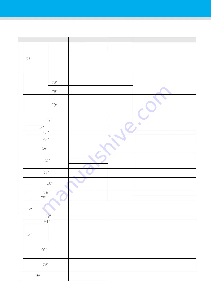
List of SET UP Functions

This section describes the overview of each function to be set and set values that can be registered in user
types.

Function name

Set value

Default

Outline

PLOT SETTING

PEN ASSIGN
(

P.3-9)

PEN No.: 
1~6

Unit: A

PEN, 
SWIVEL

No.1 
B:REC.CUTTER1
No.2 B:ROLLOR1
No.3 B:

CUTTER

No.4 B:ROLLOR2
No.5 A:SWIVEL
No.6 A:PEN

This  section  describes  how  to  assign
pen numbers in the data to tools on the

unit. 

Unit: B

REC.CUTT
ER1~2, 

CUTTER,

ROLLER1
~3

AFTER PLOT

A U T O
VIEW
(

P.1-24)

OFF, KOW-LEFT, LOW-RIGHT, 
UP-LEFT, UP-RIGHT

OFF

Set the operation after the plot end.

VACUUM
(

P.1-25)

N/C, AUTO OFF

N/C

BEFORE 
PLOT

VACUUM 
ON 
(

P.1-

26)

N/C, REMOTE ON

N/C

The  vacuum  can  be  turned  on  and  off
by interlocking with the remote key.

CLOSE TIME(

P.3-20)

3~30sec

3 sec

set the time to determine the end of the
plotting data.

ORIGIN(

P.1-22)

LOW-LEFT, CENTER

LOW-LEFT

Sets the position of command origin.

ROTATION(

P.3-15)

ON, OFF

OFF

Switch the cutting direction.

Z STROKE(

P.3-16)

4~10mm, FULLUP

7mm

Set  the  height  that  the  tool  of  B  unit
rises.

SORTING(

P.3-14)

ON, OFF

OFF

This  setting  changes  the  cutting
orderand performs cutting.

CUT MODE(

P.3-21)

NORMAL

NORMAL

This is to set the cutting quality.

SHARP
FAST

UP SPEED(

P.3-22)

AUTO,  5,  10,  20,  30
cm/s

AUTO

Set  the  speed  in  which  the  carriage  is
moved when the tool is lifted.

DUMMY CUT(

P.3-18)

ON, OFF

ON

The blade edge of swivel cutter is made to
turn to a specific direction before starting
cutting, which allows dummy cutting.

OVER CUT(

P.3-25)

OFF, 0.1 ~ 1.0mm

OFF

Make the media without uncut area.

UP HIGH(

P.3-23)

50%, 75%, 100%

50%

Set the height when lifting the pen.

ADJ-PRSOFFSET
(

P.3-24)

-9~+9

0

This is used to expand the value in such
a case as when the beginning and end
part of the cut are left cut.

MARK DETECT(

P.4-7)

Set when cut the data with a register mark.

C

O

MMAND SETTING

COMMAND(

P.3-29)

MGL-IIc3

MGL-IIc3

PRIORITY
(

P.3-29)

SP, VS, AS,
FS,  ZF,  ZA,
ZO

HOST, PANEL

HOST

When this plotter and the host computer
make different settings on a same item,
this function is used to set about which
of the two must be given priority to.

OH UNIT (

P.3-30)

INITVAL, SETVAL

SETVAL

Sets  which  value  to  return  to  the  CAD
system  when  the  unit  receives  the
effective 

area 

coordinate 

output

command from the CAD system. 

GDP UNIT(

P.3-31)

0.025mm, 0.010mm

0.025mm

This setting aligns the resolution of the
unit  with  the  resolution  of  the  CAD
system used. 

BUZZER(

P.3-26)

ON, OFF

ON

With  this  you  can  control  the  key-
pressing sound.

Содержание CFL-605RT

Страница 1: ...D202786 14 Original instructions You can also download the latest manual from our website MIMAKI ENGINEERING CO LTD URL http eng mimaki co jp ...

Страница 2: ...rgency Stop 1 8 Resetting an Emergency Stop 1 8 Preparing the Cutting Panel 1 9 Attach the felt mat 1 9 Inserting the Set Guide Plates 1 9 Blades and Workpieces 1 10 Workpiece Types that Can be Cut Guide 1 10 Blade Types that Can Be Used 1 10 Mounting Tools 1 11 Mounting the Pen or Swivel Blade 1 11 Mounting the Tangential Cutter 1 14 Mounting the Grid Roller 1 16 Mounting the Reciprocating Cutter...

Страница 3: ...Tape 2 6 Fixing the Workpiece by Vacuum Adhesion 2 7 Method of fixing the sponge 2 9 Selecting Tools 2 10 Select the tool condition 2 10 Set Items 2 11 Adjusting the Blade to Match the Workpiece 2 14 Adjusting the tial Cutter 2 14 Adjusting the Swivel Blade 2 16 Making a Test Cut 2 17 Checking the Tool Status 2 18 Checking the Status Between Tools 2 20 Setting the Drawing Origin 2 23 Cutting Drawi...

Страница 4: ...Time 3 20 Other Useful Functions 3 21 Setting a Cut Quality 3 21 Setting speed of carriage movement 3 22 Height setting at the pen tool lifted 3 23 Setting of the offset value of the cutting edge correction pressure 3 24 Make the media without uncut area 3 25 Setting a KEY BUZZER 3 26 Setting a START MODE 3 27 Setting a JOG SETTING 3 28 Setting a COMMAND 3 29 Set the configurations with a computer...

Страница 5: ...t of register mark 4 11 Register Mark Detection Procedure 4 12 Continuous Cutting of Register Marks 4 13 Confirm the following when failed in cutting correctly 4 14 Alignment of MARK SENSOR 4 14 Check the sensor for the registration mark detection 4 16 Correct the light pointer position 4 19 Setting of the back side cut offset 4 20 Chapter 5 Daily Maintenance Daily Maintenance 5 2 Cutting Panel Su...

Страница 6: ... An error occurs when the data is sent 6 14 Tool lifts up the paper 6 15 Drawn lines are broken or smudged 6 15 No reciprocating movement 6 15 Problems Causing an Error Display 6 16 Non fatal Errors 6 16 Status message 6 19 Sample Cut 6 20 Perform SAMPLE CUT to Find out the Cause of Cutting Error 6 21 CFL 605RT Specifications 6 23 ...

Страница 7: ...vi ...

Страница 8: ...unications Operation of this equipment in a residential area is likely to cause harmful interference in which case the user will be required to correct the interference at his own expense In the case where MIMAKI recommended cable is not used for connection of this device limits provided by FCC rules can be exceeded To prevent this use of MIMAKI recommended cable is essential for the connection of...

Страница 9: ...ting this manual Please contact your Mimaki representative if you discover any problems in the manual We reserve the right to change this manual at any time without notice If this manual becomes unreadable due to fire or other damage contact your Mimaki representative to purchase a new copy Accessories Confirm the accessories supplied against the separate ACCESSORIES Contact your Mimaki representa...

Страница 10: ...e notes thoroughly to operate the machine properly Useful information is given with this symbol Refer to the information to operate the machine properly Indicates the reference page for related contents The symbol indicates that the instructions must be observed as strictly as the CAUTION instructions including DANGER and WARNING instructions A sign representing a precaution the sign shown at left...

Страница 11: ...ure to carry out grounding work to prevent electrical shock Use the unit under the power specifications given Be sure to connect the power cable plug to a convenient outlet grounded or fire or electric shock might occur or it may cause electrical shock The main power circuit breaker should be set ON only by personnel with sufficient knowledge about operations of this unit Leave maintenance to a se...

Страница 12: ...airs The device is too sensitive equipment so in case if you require movement of the unit please contact to our service engineer CAUTION A place exposed to direct sunlight A place that vibrates Do not install the device at a place where the temperature of the cut panel surface exceeds 60 C The cut panel can deform or break down The device will fail to give correct results if installed in a place t...

Страница 13: ...en on the labels If a warning label is illegible due to stains or has come off purchase a new one from your local distributor or our office Order No M902667 Order No M907935 Order No M905694 Order No M911958 Order No M912059 Order No M901229 Order No M911983 Order No M903239 Order No M906115 Order No M902663 ...

Страница 14: ...xiii ...

Страница 15: ...kpieces 1 10 Workpiece Types that Can be Cut Guide 1 10 Blade Types that Can Be Used 1 10 Mounting Tools 1 11 Mounting the Pen or Swivel Blade 1 11 Mounting the Tangential Cutter 1 14 Mounting the Grid Roller 1 16 Mounting the Reciprocating Cutter 1 17 Attach the Work Holder 1 19 Local Status Remote Status 1 20 Local Status and Displays 1 20 Remote Status and Displays 1 20 Matching the PC Specific...

Страница 16: ...ce is available Allow no objects inside the installation space These may cause you to trip Model Width Depth Height Total weight CFL 605RT 1 310 mm 1 030 mm 1 100 mm Less than 109 kg 300 mm or more 300 mm or more 300 mm or more 1 910 mm or more 2 330 mm or more 1 000 mm or more 140 mm ...

Страница 17: ...r If you move by pressing the location other than mark the cover may be broken 4 Lock the caster 5 Lower the adjuster foot to perform a leveling of the machine When the machine is moved to any place other than on the same step free floor contact your distributor or our service office If you move it by yourself failure or damage may occur Be sure to request your distributor or our service office to...

Страница 18: ...OFF 8 Roll bar Set the roll of adsorption sheet on top of the two bars P 2 9 9 EMERGENCY switch Press in the event of an emergency The power is forcibly cut to stop unit operation 10 Set guide plates Guides for mounting the workpiece P 1 9 1 1 Cutting panel Felt mat Holds the workpiece It offers a regular array of small holes for vacuum adhesion P 1 9 12 LAN connector LAN interface connector P 1 7...

Страница 19: ...ight of mark sensor P 4 11 2 Register mark height fixing screw Used adjust the reading height of mark sensor P 4 11 3 Register mark sensor Light pointer Sensor to detect register marks Used for positioning to read register marks 4 Unit B Mounts the reciprocating cutter holder P 1 16 5 Unit A Holds the pen and swivel blade P 1 11 1 2 3 3 4 5 ...

Страница 20: ...T key Execute a test cut TOOL key Change the tool and set the cut conditions DATA CLEAR key Execute the data clear Jog keys Move the head in the direction of the arrow when the local menu is displayed VACUUM key Turns vacuum adhesion of the workpiece on P 2 7 VIEW key The head is saved to the set location When pressed during jog can set the axis alignment P 3 6 COPY key Re cut the data once cut in...

Страница 21: ... power before connecting the vacuum signal cable RS 232C interface cable or USB interface cable Failure to turn off the power may result in electric shocks or damage to the unit If use in Japan use at single phase 100V 120V If use at single phase AC200V please consult your service engineer Be sure to connect the ground wire Using without the ground wire causes the damage of this device and electri...

Страница 22: ...respectively Applying an Emergency Stop 1 Press the EMERGENCY switch Operation stops and the unit turns off Resetting an Emergency Stop 1 Turn the EMERGENCY switch clockwise to unlock it 2 Press the POWER switch Unit operation starts Wait at least 30 seconds after turning OFF the power before resetting an emergency stop Failure to do so may result in unit malfunctions ...

Страница 23: ...oles When using a reciprocating cutter please use by placing a felt mat or hard mat on top of the cutting mat Please use properly felt mat hard mat by the work P 1 10 Make sure to firmly insert the set guide plate into the hole of the cut panel surface When the power is turned on while some area of the set guide plate floats the set guide plate may be hit by the head and may cause the head damage ...

Страница 24: ... High speed steel blade 30 SPB 0043 Carbide blade 30 SPB 0045 Tangential cutter holder 2N SPA 0261 Swivel Blade SPB 0030 Cutter holder SPA 0090 PVC film Swivel Blade SPB 0030 Cutter holder SPA 0090 Artificial leather High speed steel blade 30 SPB 0043 Carbide blade 30 SPB 0045 Tangential cutter holder 2N SPA 0261 Urethane form Sponge 10mm Reciprocating cutter 2 x10 SPB 0086 Or Carbide blade 7x15 S...

Страница 25: ...icable Tools See page A Pen swivel cutter holder swivel cutter holder C P 1 11 B Grid roller P 1 16 Reciprocating cutter P 1 17 Tangential cutter P 1 17 Don t touch the cutter blade with your fingers Sharp cutter tip may injure you After setting the cutter do not shake the cutter holder The tip of the cutter may pop out and may injure you Keep the cutter out of reach of children Dispose of the use...

Страница 26: ...ade Follow steps 1 3 to replace the blade 2 Adjust the amount that the blade protrudes For details about the adjustment see P 2 14 Fix the cutter holder firmly If not accurate and high quality cutting plotting will not be achieved Install the cutter holder to the tool holder of the carriage Be sure to insert the cutter holder all the way in the tool holder The dedicated cutter blade is built in th...

Страница 27: ...holder presser 4 Insert the pen adapter with the pen into the tool holder Make sure that the brim of the pen adapter is rested on the tool holder Set the adapter in such a way that the fixing screw will not obstruct operation Press the brim of the pen adapter with the holder presser 5 Fix the tool Rotate the knob clockwise to fix firmly When you replace the ballpoint pen SPB 0726 contact a distrib...

Страница 28: ...e tweezers supplied Insert the blade into the holder keeping it in the direction shown in the diagram 3 Tighten the cutter stopper Turn the cutter stopper clockwise to tighten it Do not touch the blade with bare hands This may cause injury When mounting an NT high speed blade use the hand lapper supplied to round off the tip and grind down the ridge Grinding off the ridge allows the blade to fit p...

Страница 29: ...tter holder into the unit 1 Loosen the stopper screw With the supplied hexagon wrench 2 0mm fasten temporarily the supplied stopper screw in the holder 2 Insert the Unit B pin into the groove in the cutter holder 3 Use the 2 0 mm hexagonal wrench supplied to tighten the stopper screw Firmly fasten the cutter holder Correct quality may not be achieved if the stopper screw is not fully tightened Mak...

Страница 30: ...r to scribe holder 3 Fixed with set screws 2 Insert the Unit B pin into the groove in the grid roller 3 Use the 2 0 mm hexagonal wrench supplied to tighten the stopper screw Firmly fasten the cutter holder Correct quality may not be achieved if the stopper screw is not fully tightened Grid holder Grid roller Stopper screw Groove Flat part Align the pin and groove ...

Страница 31: ...mly push the blade as far as possible into the cutter holder For safety handle the blade with the tweezers supplied Attention to the flat part of the holder setscrews and the direction of the blade and attach as shown in the figure 3 Tighten the stopper screw and clamp the blade Do not touch the blade with bare hands This may cause injury A reciprocating cutter holder is required to mount the reci...

Страница 32: ...B fixing screw Turn the fixing screw counterclockwise to loosen it The fixing screw is 4 mm long It will fall out of Unit B if it is loosened too much 4 Tighten the fixing screw Push the cutter holder firmly upwards to eliminate any clearance between the lug on Unit B and the groove in the reciprocating holder and then tighten the fixing screw Firmly fasten the cutter holder If the holder is loose...

Страница 33: ... works sponges etc do not use the work holder The work holder is designed to hold works such as corrugated fiberboard When using a work holder be sure that overall bottom surface is flat against the work If bottom surface run off the work edge in a case cutting edge of a work cutter does not down and may not cut correctly When installing the work holder press against the mounting surface of the wo...

Страница 34: ... and are enabled on the operation screen panel The following three screens appear in the remote status Recipro Cutter Grid Roller Selected This remote screen appears when Unit B TOOL Rec Cutter 1and 2 Cutter Roller1 to 3 is selected for TOOL SELECT in the local menu S start offset and E end offset do not appear when the grid roller is selected 1 Display the current number total number during runni...

Страница 35: ...screen appears when HEAD A or TOOL SWIVEL is selected for TOOL SELECT in the local menu 1 Display the current number total number during running the number of cutting PRS Cutting pressure SPD Cutting speed REMOTE KB A PEN REMOTE SPD 3 0 cm s PRS 6 0 g 1 PRS Cutting pressure SPD Cutting speed OFS Offset value REMOTE KB A SWI VE L REMOTE KB SPD 3 0 cm s PRS 1 0 0 0 g REMOTE KB OFS 0 3 0mm 1 ...

Страница 36: ... LOCAL 2 Press to select SET UP and press the key 3 Press to select PLOT SETTING 4 Press the key 2 Press the jog key or to select ORIGIN and ress the key 3 Press the jog key or to select Setting Set values LOW LEFT CENTER 4 Press the key Press if you do not want to save the setting 5 Press the key twice for terminating this function Item Set value LOW LEFT Lower left of the maximum effective cutti...

Страница 37: ...tching the Plotter Specifications This unit uses the command MGL IIC3 Set the CAD command to connect to the unit to MGL IIC3 Only the MGL IIC3 commands are available in MODE SET This command cannot be changed at the plotter ...

Страница 38: ...y 3 Press the jog key or to select AUTO VIEW and ress the key 4 Press the jog key or to select retraction position Set values OFF LOW LEFT LOW RIGHT UP LEFT UP RIGHT 5 Press the key Press if you do not want to save the setting 6 Press the key twice for terminating this function Item Set value OFF No automatic retraction 1 LOW LEFT Save to the lower left 2 LOW RIGHT Save to the lower right 3 UP LEF...

Страница 39: ...t setting Set values N C AUTO OFF 5 Press the key Press if you do not want to save the setting 6 Press the key twice for terminating this function Item Set value AUTO OFF 1 1 The vacuum cannot turn off automatically if automatic head retraction is OFF If automatic head retraction is set to available the vacuum turns off automatically after head retraction N C Vacuum remains on after head retractio...

Страница 40: ...s to select PLOT SETTING 7 Press the key 2 Press the jog key or to select BEFORE PLOT and ress the key 3 Press the key 4 Press the jog key or to select REMOTE ON Set values N C REMOTE ON 5 Press the key Press if you do not want to save the setting 6 Press the key twice for terminating this function Item Set value REMOTE ON When the remote mode is selected by pressing the remote key the vacuum is a...

Страница 41: ...ion 2 7 Method of fixing the sponge 2 9 Selecting Tools 2 10 Select the tool condition 2 10 Set Items 2 11 Adjusting the Blade to Match the Workpiece 2 14 Adjusting the tial Cutter 2 14 Adjusting the Swivel Blade 2 16 Making a Test Cut 2 17 Checking the Tool Status 2 18 Checking the Status Between Tools 2 20 Setting the Drawing Origin 2 23 Cutting Drawing 2 24 Effective Cutting Area 2 24 Cutting D...

Страница 42: ...the Head P 2 4 3 Fixing the Workpiece See Fixing the Workpiece P 2 6 4 Setting the tool conditions See Selecting Tools P 2 10 5 Select the tool condition See Select the tool condition P 2 10 6 Making a Test Cut See Making a Test Cut P 2 17 7 Setting the Drawing Origin See Setting the Drawing Origin P 2 23 8 Cutting Drawing See Cutting Drawing P 2 24 9 Turning the power off See Turning the power on...

Страница 43: ...anel When the power is turned ON the head moves to the low right retraction point The head may be damaged if it hits an object Please lift up the mark sensor before turn on the power When the power is turned on by setting the felt mat while lowering the mark sensor the set guide plate may be hit by the head and may cause the head damage Make sure that the set guide plate is firmly inserted into th...

Страница 44: ...e table each corner or the drawing origin 1 Press the key in LOCAL 2 Press and select the retracted position Set value LOW LEFT LOW RIGHT ORIGIN UP LEFT UP RIGHT 3 Press The head retracts to the designated position If Automatic Head Retraction P 1 24 is set the head automatically returns to the retraction position after cutting drawing is complete so that the View function is not required Convenie...

Страница 45: ...ordinates are displayed with respect to the command origin position 1 Select the local menu If the unit is in remote status press to set local status 2 Press a jog key once 3 Press a jog key to move the head The destination coordinates are displayed 4 Press or OR I G I N SET PEN mm X 3 0 0 0 Y 3 0 0 0 LOCA L A PEN OR I G I N SET PEN mm X 0 0 Y 0 0 OR I G I N SET PEN mm X 3 0 0 0 Y 3 0 0 0 OR I G I...

Страница 46: ...orbed in vacuum use adhesive tape and fix the workpiece Fix the four edges of the workpiece with the adhesive tape The following table shows the acceptable workpiece thicknesses Maximum value Four area stickers are stuck on the table They indicate the maximum effective cutting area Mount the workpiece inside this area The plotter is unable to cut outside the area indicated by the area stickers Use...

Страница 47: ...sorption sheet of the cut portion is peeled off from the workpiece surface and it may cause inferior in drawing 1 Press the key to suspend cut draw temporarily 2 Press the jog key to retract the head 3 Cover the adsorption sheet cut in small pieces to the portion cut earlier 4 Press the key to return to the local mode 5 Press the key and then restart the cut draw It is also possible to block the c...

Страница 48: ...2 8 1 Put the workpiece on the cutting panel 2 Press ...

Страница 49: ... a adsorption sheet to fix the work in the following ways 1 Put the workpiece on the cutting panel 2 Set a roll of adsorption sheet to roll holder 3 Pull out the adsorption sheet and cover the entire work surface 4 Press In the case of nonporous work please cut the adsorption sheet on the work If you do not cut adsorption sheet float and jam occurs Work surface ...

Страница 50: ...ss key to display the cut conition to set and press the key The displayed items differ according to the tool Set Items 7 Press key to set the setting value and press the key The setting is saved Press if you do not want to save the setting 8 To select and set another item repeat Steps 7 and 8 For details about the settings see Set Items 9 When all settings are complete press key Unit Tool A B Pen ...

Страница 51: ...ive series of line segments This reduces the degree of damage to the workpiece by the tool START CORR 0 0 0 2 50 step 0 05mm Offset for cutting start position when the tool descends When cutting a thick workpiece setting this offset to a large value cuts from the front of the workpiece to simplify separation Adjust this setting while checking the finish END CORR 0 0 0 2 50 step 0 05mm Offset for c...

Страница 52: ...arc with a radius at least 15 mm but less than 20 mm If OFF the previously set speed is used for drawing R30 SPEED OFF 1 20 cm s Speed for drawing an arc with a radius at least 20 mm but less than 30 mm If OFF the previously set speed is used for drawing R40 SPEED OFF 1 25 cm s Speed for drawing an arc with a radius at least 30 mm but less than 40 mm If OFF the previously set speed is used for dra...

Страница 53: ...t the setting value and press the key If select OFF to the set value it does not use the W roller function Set values OFF 0 1 1 0mm 8 Press key several times and finish the setting Does not draw the normal ruled line If the W roller is set other than off w will be displayed after the tool name Offset 0 1 1 0mm Offset 0 1 1 0mm Normal ruled Draw 2 ruled lines when W roller is ON TOOL SE L ECT A PEN...

Страница 54: ... A cutter holder is required to mount the tial cutter It is not possible to adjust a reciprocating cutter blade Handle the blade carefully to avoid injury For safety handle the blade with the tweezers supplied Head Type Cutter Holder Cutter Applicable Workpiece Unit B Cutter holder 2 N For high speed 30 For carbide 30 Workpiece thickness 2 mm max ...

Страница 55: ...should protrude by workpiece thickness 0 2 mm 3 Tighten the dial stopper while pushing the dial in the direction of the arrow The dial has some play To eliminate discrepancies in the amount that the blade protrudes push the dial in the direction of the arrow while tightening the dial stopper When mounting a trial cutter in Unit B select the Cutter in the Tool Select P 2 11 If use with the setting ...

Страница 56: ...justing the blade edge set the cut condition and perform test cut to check whether cutting is performed well 1 Turn the adjusting knob to adjust the protruding amount of the cutter The blade protrudes when turn the adjustment knob clockwise 0 5 mm per revolution Cutter Adjusting knob ...

Страница 57: ...mpleted the screen returns to LOCAL 3 Check the cutted test pattern When the result is normal end the operation No Check Item Check Point 1 Are the cutting drawing conditions suitable Work is correcly cut or drawing is not smudged 2 Is tool mounted eccentrically An eccentric tool can cause displacement in the cutting or drawing 3 Do tools match When a tial cutter cuts over a drawing do the drawn a...

Страница 58: ...ditions Increase the END CORR P 2 11 Blade is mounted eccentrically Conduct Adjust Eccentricity in tool adjustments P 6 4 Lines displaced at Point A Abnormal angle of tial cutter Conduct Adjust in tool adjustments P 6 9 Cutting incomplete Press value low Increase the PRESSURE in the cutting conditions P 2 11 Cutting incomplete at corners The START CORR and END CORR values in the cutting conditions...

Страница 59: ...flutes of corrugate cardboard Y PRESS value in the cutting conditions is too high Align the corrugated cardboard flutes in the Y axis direction Decrease the Y PRESS in the cutting conditions P 2 11 Check Point Cause Remedy See page Broken lines Swivel cutter incorrectly mounted Fully tighten the holder screw P 1 13 Speed is too slow Increase the SPEED in the cutting conditions P 2 12 Press value l...

Страница 60: ...the items requiring adjustment The description below refers to the pen and tial cutter For the crease roller read tial cutter as crease roller Overview The tial cutter is displaced with respect to the center of the pen regardless of the direction of movement Remedy Adjust the Offset in Adjust Cutter in tool adjustments P 6 3 Overview The cut is rotated clockwise or counterclockwise Remedy Conduct ...

Страница 61: ...ight of the direction of movement Remedy Adjust Pattern B for Adjust Eccentricity in Adjust Cutter in tool adjustments P 6 3 Overview The cut is rotated clockwise or counterclockwise and the cutting start point is too far forward or backward Remedy See the remedies described for Sample B and Sample C Overview The cut is rotated clockwise or counterclockwise and the tial cutter is displaced to the ...

Страница 62: ...e cutting end point is too long or too short and the tial cutter is displaced to the right or left Remedy See the remedies described for Sample D and Sample E Overview The cut is rotated clockwise or counterclockwise the cutting end point is too long or too short and the tial cutter is displaced to the right or left Remedy See the remedies described for Sample B Sample D and Sample E Sample H Samp...

Страница 63: ...enter the jog mode Press either one of the jog keys and you can enter the jog mode 3 Press the jog key or to set the origin 4 Press the key to decide the origin After displaying the effective cutting for while the plotter returns to the local mode The origin is set as coordinate position 0 0 When the head is moved by pressing the jog keys the screen displays the coordinates with respect to the ori...

Страница 64: ...s automatically after the data is received When cutting is complete the display appears as shown to the right Model Name X axis mm Y axis mm CFL 605RT 610 510 When the mark sensor is lowered the warning screen is shown in the display in the right Make sure the height of mark sensor matches with the workpiece Press the key X axis Y axis Maximum effective cutting area Ch e c k MARK SENSOR h e i g h ...

Страница 65: ...during drawing cutting or grid cutting in remote status for any reason 1 Press during unit operation Restarting Processing 1 Press The unit enters remote status and processing restarts Functions that Can Be Set After Interrupting Processing Clear the data remaining in the receive buffer P 2 26 Interrupting Processing Data Clear ...

Страница 66: ...e receive buffer 3 To clear data remaining in the receive buffer before receiving data from running the SINGLE COPY function 4 To cut using a PC that is different from the PC that sent the cutting data the previous time 1 Set local status If the unit is in remote status press to set local status Press during data processing to interrupt the processing 2 Press 3 Press The data is cleared Press to c...

Страница 67: ...ch to turn the power OFF Push the power switch located on the operation panel Power lamp goes off and power turns off 3 Set the power switches located on the right side of this machine to the O side Checking Uncut Data To cut the data 1 Press to select remote status 2 Received data volume is displayed and cutting drawing starts To delete the data 1 Press to select local status 2 Clear the data P 2...

Страница 68: ...2 28 ...

Страница 69: ... Units 3 17 Swivel Blade Dummy Cut 3 18 Setting the Displayed Language DISPLAY 3 19 Setting the Close Time 3 20 Other Useful Functions 3 21 Setting a Cut Quality 3 21 Setting speed of carriage movement 3 22 Height setting at the pen tool lifted 3 23 Setting of the offset value of the cutting edge correction pressure 3 24 Make the media without uncut area 3 25 Setting a KEY BUZZER 3 26 Setting a ST...

Страница 70: ... CUT MODE P 3 21 NORMAL NORMAL This is to set the cutting quality SHARP FAST UP SPEED P 3 22 AUTO 5 10 20 30 cm s AUTO Set the speed in which the carriage is moved when the tool is lifted DUMMY CUT P 3 18 ON OFF ON The blade edge of swivel cutter is made to turn to a specific direction before starting cutting which allows dummy cutting OVER CUT P 3 25 OFF 0 1 1 0mm OFF Make the media without uncut...

Страница 71: ...ble when both of DHCP and AutoIP are OFF Set the IP address used by this machine Def Gateway 2 2 Settable only when Auth is not OFF Set the default gateway used by this machine DNS Address 2 Set the DNS server address used by this machine SubNetMask 2 Set the digit number of the subnet mask used by this machine EVENT MAIL P 3 36 Delivery ON OFF When the set event occurs the function to send the e ...

Страница 72: ...ore SMTP Set the SMTP server authentication method SMTP Auth OFF User Name 1 1 Settable only when Auth is not OFF Set the user name used for the authentication Pass Word 1 Set the password used for the authentication POP3 Addr 2 2 Settable only when Auth is POP before SMTP Set the POP server APOP 2 OFF Set ON OFF of APOP TEST Send the test e mail SETTING COPY P 3 45 Copy the set value to other use...

Страница 73: ...ter will start cutting plotting P 3 5 Two point axis alignment If a ruled sheet is set align the horizontal and vertical axes with the appropriate lines on the sheet P 3 6 Cutting area Set the area in which the plotter performs cutting plotting P 3 7 Up and Down of the Pen This is to put up and down the tool Press the key in the jog mode Before you set the function in the jog mode be sure to confi...

Страница 74: ...cutting plotting 2 Set the Origin by pressing the jog key or to and press the key 3 Press the jog key or to enter the jog mode Press either one of the jog keys and you can enter the jog mode 4 Press the key 5 Press the jog key or to set the compensation point θ 45 degrees to 45 degrees 6 Press the key to decide the origin The display is as shown on the right briefly after which the plotter returns...

Страница 75: ...e jog key or to enter the jog mode Press either one of the jog keys and you can enter the jog mode 3 Press the key 4 Press the jog key or to set the point UR 5 Press the key to decide the point UR The display is as shown on the right briefly after which the plotter returns to the local mode Be sure to set the upper right point in the area located in the normal direction from the origin Be sure to ...

Страница 76: ...the pen tip reaches a given point of the pattern The coordinates relative to the origin will be displayed If you set the step to a smaller value using the jog step function you may select a desired point with increased accuracy P 3 28 3 Press the key The plotter records the point of the pen head The plotter receives the coordinate output command OD from the host computer The digitization operation...

Страница 77: ...LOT SETTING 4 Press the key 2 Press the jog key or to select PEN ASSIGN and ress the key Tool name displays the current settings 3 Press the jog key or and select the pen number to be set Here select pen number 1 Set values 1 to 6 4 Press the key 5 Press the jog key or to select unit Here choose the unit A Set values A B 6 Press the key 7 Press the jog key or to select tool The set values differ a...

Страница 78: ...unted tools Here choose the tool REC CUTTER1 Unit A PEN SWIVEL Unit B REC CUTTER1 to 2 CUTTER ROLLER1 to 3 15 Press the key If set the other pen number repeat the operation from step 5 to 10 16 Press the key twice for terminating this function The initial value of each pen number is as follows PEN No SE L ECT No 1 A PEN PEN No SE L ECT No 2 B ROL L ER1 PEN ASS I GN No 2 B ROL L ER1 PEN ASS I GN No...

Страница 79: ...Reset the origin to the position to be copied Failure to reset the origin results in cutting at the same position 5 Press 6 Press to copy the data Press to cancel the copy When copying is complete the display reverts to the remote status Head withdrawal follows the setting of AFTER PLOT AUTO VIEW P 1 24 To cut once more repeat the procedure from Step 4 Use DATA CLEAR to clear P 2 26 the receive bu...

Страница 80: ...9 Set the number of copies you want to cut 2nd PRESS 30 g to 1500 g 1 1 The set values differ according to the unit REC CUTTER CUTTER ROLLER 500 g to 1500 g When vibration is on 1500g fixed SWIVEL 30 g to 1000 g Sets the press value for the second cut 3rd PRESS Sets the press value for the third cut 4th PRESS Sets the press value for the fourth cut 5th PRESS Sets the press value for the fifth cut ...

Страница 81: ...set the pressure value for each cut number In order to make the multi pass cutting with FineCut function set Off in step 6 and set at the output setting in FineCut If the multi pass cutting is set in both FineCut and the machine the number will be duplicated Example 3times in the machine side and 2 times in FineCut will be 6 times in total If the multi pass cut is set the drawing starts from the r...

Страница 82: ...ding to each cutting operation that starts with pen down and ends with pen up as one block After the completion of cutting one block the plotter will perform cutting of another block whose starting point is closest to the finished block For data transmitted from the host computer the starting position and cutting direction will not be changed Starting point of data Starting point of cutting Arrow ...

Страница 83: ... the movement of the origin at the same time OFF Does not perform the rotation 4 Press the key Press if you do not want to save the setting 5 Press the key twice for terminating this function Confirm that any data to be cut is not saved in the receiving buffer If you change the set values the contents of the receiving buffer are cleared completely Rotation cannot be enabled if the register mark de...

Страница 84: ... the set up menu 1 Press the key in LOCAL 2 Press to select SET UP and press the key 3 Press to select PLOT SETTING 4 Press the key 2 Press the jog key or to select Z STROKE and ress the key 3 Press the jog key or to select setting value Set values 4 to 10 mm FULLUP 4 Press the key Press if you do not want to save the setting 5 Press the key twice for terminating this function FUNCTION P LOT SET T...

Страница 85: ...e jog key or to select MM INCH and ress the key 4 Press the jog key or to select setting value Set values mm inch 5 Press the key Press if you do not want to save the setting 6 Press the key twice for terminating this function Set value Description mm Displays millimeters inch Displays inches FUNCT I ON SET UP ENT FUNCTION SET UP P LOT SET T I NG ENT P LOT SET T I NG MM I NCH mm P LOT SET T I NG M...

Страница 86: ... up menu 1 Press the key in LOCAL 2 Press to select SET UP and press the key 3 Press to select PLOT SETTING 4 Press the key 2 Press the jog key or to select DUMMY CUT and ress the key 3 Press the jog key or to select setting value Set values OFF ON 4 Press the key Press if you do not want to save the setting 5 Press the key twice for terminating this function Set value Description OFF Makes no dum...

Страница 87: ... the key in LOCAL 2 Press and select DISPLAY 3 Press 4 Press and select TOOL Set value CUTTER ROLLER SWIVEL 5 Press the key Press if you do not want to save the setting 6 Press the key twice for terminating this function FUNCT I ON SET UP ENT FUNCTION FUNCT I ON D I SPY ENT D I SPY L ANG E n g l i s h D I SPY L ANG J a p a n e s e ...

Страница 88: ... PLOT SETTING of the set up menu 1 Press the key in LOCAL 2 Press to select SET UP and press the key 3 Press to select PLOT SETTING 4 Press the key 2 Press the jog key or to select CLOSE TIME and ress the key 3 Press the jog key or to select the set value Set values 3 s to 30 s 4 Press the key Press if you do not want to save the setting 5 Press the key twice for terminating this function FUNCTION...

Страница 89: ...to give priority to cutting quality FAST This is used to perform cutting in a short time 4 Press the key Press if you do not want to save the setting 5 Press the key twice for terminating this function Select QUALITY in any of the following cases a Characters whose sizes are 10 mm or less are to be cut b Picture patterns or characters that have many sharp corners are to be cut c Minute cutting is ...

Страница 90: ...SET UP and press the key 3 Press to select PLOT SETTING 4 Press the key 2 Press the jog key or to select UP SPEED and press the key 3 Press the jog key or to select Setting Set values AUTO 5 10 20 30cm s 4 Press the key Press if you do not want to save the setting 5 Press the key twice for terminating this function FUNCTION P LOT SET T I NG UP SPEED AUTO P LOT SET T I NG UP SPEED 1 0 cm s ...

Страница 91: ...OT SETTING 4 Press the key 2 Press the jog key or to select UP HIGHT and press the key 3 Press the jog key or to select Setting For thick media or when the cutter scratches the media because the sheet is not flat set the amount of lifting bigger Set values 50 75 100 4 Press the key Press if you do not want to save the setting 5 Press the key twice for terminating this function FUNCTION P LOT SET T...

Страница 92: ...o select SET UP and press the key 3 Press to select PLOT SETTING 4 Press the key 2 Press the jog key or to select ADJ PRS OFFSET and ress the key 3 Press the jog key or to select Setting Set values 9 9 Around 30g to around 30g 4 Press the key Press if you do not want to save the setting 5 Press the key twice for terminating this function FUNCTION P LOT SET T I NG AD J PRS OF FSET 0 P LOT SET T I N...

Страница 93: ...OT SETTING of the set up menu 1 Press the key in LOCAL 2 Press to select SET UP and press the key 3 Press to select PLOT SETTING 4 Press the key 2 Press the jog key or to select OVER CUT and ress the key 3 Press the jog key or to select OVER CUT setting Setting value OFF or a value from 0 1 to 1 0mm 0 1mm unit 4 Press the key Press if you do not want to save the setting 5 Press the key twice for t...

Страница 94: ... Press the key 6 Press to select ON OFF 7 Press the key 8 Press the key several times to end the setting When the key buzzer is set to OFF the buzzer sound for errors warnings operation completion etc cannot be shut off FUNCT I ON SET UP ENT FUNCTION FUNCT I ON SET UP ENT SET UP P LOT SET T I NG ENT SET UP BUZ ZER ON SET UP BUZ ZER ON SET UP BUZ ZER OF F SET UP BUZ ZER OF F ...

Страница 95: ...ress the key 4 Press to select START MODE 5 Press the key 6 Press to select LOCAL REMOTE Set values LOCAL REMOTE 7 Press the key 8 Press the key several times to end the setting FUNCT I ON SET UP ENT FUNCTION FUNCT I ON SET UP ENT SET UP P LOT SET T I NG ENT SET UP START MODE LOCA L SET UP START MODE LOCA L SET UP START MODE REMOTE SET UP START MODE REMOTE ...

Страница 96: ...m movement per jog key operation 1 0mm 1 0mm movement per jog key operation Set values Set in inch 1 16inch 1 16 inch movement per jog key operation 1 254inch 1 254 inch movement per jog key operation 7 Press the key 8 Press the key several times to end the setting FUNCT I ON SET UP ENT FUNCTION FUNCT I ON SET UP ENT SET UP P LOT SET T I NG ENT SET UP JOG SET T I NG ENT JOG SET T I NG JOG STEP 0 1...

Страница 97: ...Press the key 1 Press the jog key or to select Setting Set values HOST This is to give priority to the setting of host computer PANEL This is to give priority to the setting of this plotter If set other items repeat the procedure from step 4 to 7 6 Press the key Press if you do not want to save the setting 7 Press the key several times to end the setting SP Pen selection command VS Pen lowering sp...

Страница 98: ... cut area 1 Select COMMAND SETTING of the set up menu 1 Press the key in LOCAL 2 Press to select SET UP and press the key 3 Press to select COMMAND SETTING 4 Press the key 2 Press the jog key or to select OH UNIT 3 Press the key 4 Press the jog key or to select Setting Set values INITVAL SETVAL 5 Press the key Press if you do not want to save the setting 6 Press the key several times to end the se...

Страница 99: ...ess the key in LOCAL 2 Press to select SET UP and press the key 3 Press to select COMMAND SETTING 4 Press the key 2 Press the jog key or to select GDP UNIT 3 Press the key 4 Press the jog key or to select Setting Set values 0 025mm 0 010mm 5 Press the key Press if you do not want to save the setting 6 Press the key several times to end the setting 1 GDP Graphic Display Pitch FUNCTION COMMAND SET T...

Страница 100: ...alues 1200 2400 4800 9600 19200 38400 bps 5 Press the key 6 Press the jog key or to select the following items The following items are provided for the setting of registration mark detection Data bits Parity Stop bits Handshake See pages P 3 33 for the contents of each setting item 7 Press the key 8 Press the jog key or to select the set values See pages P 3 33 for the contents of each setting ite...

Страница 101: ...ns 9 Press the key to confirm the value 10 When you want to terminate this procedure press the key twice Setting Items Boud rate 1200 2400 4800 9600 19200 38400 bps Data bits 7 8 bit Parity NON EVEN ODD Stop bits 1 2 bit Handshake HARD ENQACK X PRM SOFT ...

Страница 102: ... 4 Press the key The IP address currently used by this machine is displayed 5 Press the key 6 Press the jog key or to select MAC Address 7 Press the key The MAC address currently used by this machine is displayed When you press the remaining address is displayed 8 Press the key After connecting with the network it takes time until the IP address is determined If the IP address has not been determi...

Страница 103: ... DHCP has priority 14 Press the key 15 Press the jog key or to select the set values Both of DHCP and AutoIP is OFF you can set IP Address Default Gateway DNS Address Sub Net Mask For other than above proceed to the Step 21 16 Press the key 17 Press the jog key to select the set values 18 Press the key to confirm the value 19 Press the key several times for terminating this function To reflect net...

Страница 104: ...select EVENT MAIL 3 Press the key 4 Press the key 5 Press the jog key or to select ON 6 Press the key 7 Press the key several times for terminating this function Disclaimer The customer is responsible for the communication fee for Internet communication such as e mail notification The notification by the event mail function may not be delivered due to Internet environment failure of the device the...

Страница 105: ...Press to set ON OFF 6 Press the key Set whether you send do not send the e mail at the end of plotting Press to set ON OFF 7 Press the key Set whether you send do not send the e mail when an error occurs Press to set ON OFF 8 Press the key Set whether you send do not send the e mail when a warning occurs Press to set ON OFF 9 Press the key 10 Press the key several times for terminating this functi...

Страница 106: ...the jog key or to select Mail Addr 5 Press the key 6 Press the jog key to set mail address Set the e mail address to which you send the event mail Set it with alphanumeric characters and symbols within 96 characters 7 Press the key 8 Press the key several times for terminating this function FUNCTION I NTER FACE EVENT MA I L ENT EVENT MA I L De l i v e r y ENT EVENT MA I L Ma i l A d d r EN T Ma i ...

Страница 107: ...s the key 4 Press the jog key or to select Subject 5 Press the key 6 Press the jog key to set subject Set the characters to write in the subject of the event mail Set it with alphanumeric characters and symbols within 8 characters 7 Press the key 8 Press the key several times for terminating this function FUNCTION I NTER FACE EVENT MA I L ENT EVENT MA I L De l i v e r y ENT EVENT MA I L S u b j e ...

Страница 108: ...key 6 Press the key Press the jog key to set SMTP server Input the SMTP server name or IP address 7 Press the key 8 Press the jog key or to select SMTP PORT 9 Press the key 10 Press the jog key or to set Auth 11 Press the key FUNCTION I NTER FACE EVENT MA I L ENT EVENT MA I L De l i v e r y ENT EVENT MA I L S e r v e r ENT SERVER SETUP SMTP A d d r ENT SMTP A d d r e s s SERVER SETUP SMTP A d d r ...

Страница 109: ... User Name 20 Press the key Press to set the user name to use for the authentication Set it with alphanumeric characters and symbols within 30 characters 21 Press the key 22 Press the jog key or to select Pass Word Depending on your server if you do not set the e mail address not supporting the account sending receiving e mails may be unavailable SERVER SETUP SENDER A s s r ENT S e n d e r Ma i l ...

Страница 110: ... jog key to set POP server Set the server name or the IP address 27 Press the key 28 Press the jog key or to select APOP 29 Press the key Press to set ON OFF of APOP 30 Press the key 31 Press the key several times for terminating this function On the password setting screen the value currently set is not displayed Only you can do is to enter the value newly P a s s Wo r d SERVER SETUP U s e r Name...

Страница 111: ...y 4 Press the jog key or to select Test 5 Press the key 6 Press the key The sent result is displayed If sending test e mail has failed an error code is displayed Refer to the next page to solve the problem 7 Press the key several times for terminating this function FUNCTION I NTER FACE EVENT MA I L ENT EVENT MA I L De l i v e r y ENT EVENT MA I L TEST E N T T r a n sm i t T e s EXECUTE E N T T r a...

Страница 112: ...P server setting Check the firewall setting 12010 An error returns from the POP server Check the POP server setting 13000 The POP authentication has failed Check the user name and the password Check the APOP setting 10013 10014 The SMTP server cannot be found Or cannot access DNS server Check the SMTP server address Check that the machine is in the environment where DNS is available 10021 Cannot c...

Страница 113: ...IG CUT COND MULTI PASS 7 Press the key 8 Press the jog key or to select the user setting number to copy Set values 1 to 4 Temp 9 Press the key From the selected user copy the settings that you selected in step 4 10 Press the key two times for terminating this reset operation FUNCT I ON SET UP ENT FUNCTION FUNCT I ON SET UP ENT SET UP P LOT SET T I NG ENT SET UP SET T I NG COPY ENT SET T I NG COPY ...

Страница 114: ...TUP RESET 5 Press the key This is to initialize the setting items and parameters Initialized items SET UP MULTI PASS and CUT CONDITION 6 Press the key three times to stop and end initialization Initialize the current user setting Other user settings are not initialized FUNCT I ON SET UP ENT FUNCTION FUNCT I ON SET UP ENT SET UP P LOT SET T I NG ENT SET UP SETUP RESET ENT SETUP RESET OK Y ENT N END...

Страница 115: ...ser Set values 1 to 4 Temp 5 Press the key 6 Press the key twice for terminating this function You cannot change the user while the cutting operation stops First clear data and then change the user Temp user does not save the settings Please use if you do not want to change the existing settings such as a temporary test cut Setting of Temp user is initialized when the power is turned on again If c...

Страница 116: ...plays the serial number of the machine IP Address This displays the IP address of the machine F W ver This displays the firmware version of the machine Command Ver This displays the command version of the machine MODEL Displays model name Serial No Displays serial number IP address Displays IP address in use F W version Displays firmware version FUNCT I ON SET UP ENT FUNCTION FUNCT I ON I NFORMAT ...

Страница 117: ...4 6 Setting Register Mark Detection 4 7 Precautions Related to Register Mark Detection 4 7 Setting Register Mark Detection 4 9 Detecting Register Marks 4 10 Using the Light Pointer to Check the Workpiece Tilt 4 10 Setting height of register mark 4 11 Register Mark Detection Procedure 4 12 Continuous Cutting of Register Marks 4 13 Confirm the following when failed in cutting correctly 4 14 Alignmen...

Страница 118: ...nowledge required when creating register marks Size of Register Marks See Guide to Register Mark Separation and Register Mark Size P 4 5 for guidelines on a side length of register marks with respect to the data The register marks described here are used to detect the work orientation and the lengths of the X and Y axes They are not crop marks Set a side length of the register mark between 5 mm an...

Страница 119: ...false detection or incorrect reading of the register marks may occur When place a register mark outside the cut area the end of the workpiece turn on the setting of MARK FILLUP P 4 8 Mark Form Type 1 Mark Form Type 2 False detection of the register marks causes displacement of the cutting position Work piece More than 10mm from left end of work piece Maximum effective cutting area Permitted Arrang...

Страница 120: ... Register Marks Example 2 Square register marks TP3 of Pattern A and TP1 of Pattern C TP2 of Pattern A and TP1 of Pattern B are not separated by at least 10 mm Therefore when using offset printing print the register marks on only one of the four CMYK plates such as printing register marks as K100 Printing the register marks on one plate only eliminates concerns about plate displacement Determine a...

Страница 121: ...Separation and Register Mark Size The chart below shows a guide to the register mark separation A and register mark size B The register marks may not be detected correctly if the register mark size B is too small with respect to the register mark separation A Create register marks of an appropriate size A 200 mm max 500 mm B 10 mm 15 mm Prohibited drawing area Prohibited drawing area Separate by a...

Страница 122: ...white background The registration mark will not be detected correctly if the background is not white or the mark is not black Bleeding or Smudging of Register Marks If the mark is blurred a wrong mark origin can be detected thus resulting in deviated cutting Good No Good Register mark Normal Register mark There is bleeding ...

Страница 123: ...n the Y direction 3 pt Detects TP1 TP2 and TP3 Conducts tilt correction and scale correction in the X direction and Y direction 4 pt Detects TP1 TP2 TP3 and TP4 Conducts tilt correction and 4 point scale correction SCALE OFF 1 1 Set to OFF when using FineCut No scale correction during register mark detection after Enter the X and Y sizes in the data after register mark detection to correct the sca...

Страница 124: ...lower the sensitivity Generally use it with the setting value of 4 MARK FILLUP ON OFF Specify the setting as ON when using the Fill around the register mark function of FineCut to detect the printed registration mark Create using a registration mark size of 10 mm or more when filling in around the registration mark Backside Data Cut CUT TOOL REC CUTTER1 2 Cutter SWIVEL When performing the backside...

Страница 125: ...are provided for the setting of registration mark detection SCALE SIZE OFFSET X OFFSET Y FORM COPIES X COPIES Y DETECT MODE SENSOR LEVEL MARK FILLUP and Backside Data Cut See pages P 4 7 through P 4 8 for the contents of each setting item 9 Press the key 10 Press the jog key or to select the set values See pages P 4 7 through P 4 8 for the contents of each setting item 11 Press the key to confirm ...

Страница 126: ...nter lights By pressing the jog keys to move the light pointer between points TP1 and TP2 the tilt of the workpiece can be checked from the light pointer line Adjust the tilt of the workpiece to this line If the workpiece has curled flatten it out If using cutting software that does not offer register mark functions ensure that the areas between TP1 and TP3 and between TP1 and TP2 are free of imag...

Страница 127: ... with the register mark and release the hand from the lever Until tighten the screws hold it lowered the lever After cutting the data with mark sensor lift up the mark sensor When set a felt mat while lowering the mark sensor the set guide plate may be hit by the head and may cause the head damage Make sure that the height gauge shaft is in contact with the register mark Use always lever for verti...

Страница 128: ...ected Mount the workpiece again 5 After the register marks are detected the SCALE CORRECT screen appears This example shows 4 point detection If the data lengths and detected lengths differ use to set them 6 Press after setting The local mode is selected If SCALE is set to before register mark detection starts Press to disable the scale correction If SCALE is set to OFF the SCALE SET screen is not...

Страница 129: ...l continuous cutting 3 Detect the register marks P 4 10 Copying starts when register mark detection is complete Repeat Step 2 and Step 3 for the designated number of cuts 4 When the designated number of workpieces has been cut and the system reverts to remote mode Head withdrawal follows the setting of AFTER PLOT AUTO VIEW P 1 24 Select multi mode when cutting plural images printed on one media Wh...

Страница 130: ...key or 5 Press the key 6 Select SENSOR OFS by pressing the jog key or 7 Press the key After detecting registration mark 1pt cut the center line of the register mark and both sides of five auxiliary lines every 0 2 mm LOCA L A SW I V E L LOCA L S E T U P E N T FUNCTION F U N C T I O N MA R K S E N S O R E N T MAR K S E N S O R S E N S O R O F S E N T MAR K S E N S O R S E N S O R O F S E N T S E N ...

Страница 131: ...ion If misaligned by 0 2 mm enter 0 2 9 Press the key Registering the compensation value 10 Press the key twice for terminating this function The setting values are kept in memory even when the power is turned off The sensor offset value selected by this operation is not initialized by SETUP RESET operation S E N S O R O F F S E T X 0 2mm Y 0 2mm MA R K S E N S O R S E N S O R O F S E N T ...

Страница 132: ...eturns to the local mode 5 Press the key 6 Select MARK sensor by pressing the jog key or 7 Press the key If you move the head and sheet manually you cannot perform the right response check Be sure to perform it via the following operations For conditions of already printed registration mark refer to Precautions when Creating Data with Register Marks P 4 2 Set the buzzer sound to ON P 3 26 The regi...

Страница 133: ...k For details on setting the SIZE refer to the MARK DETECT setting procedure P 4 9 11 Press the jog key or to select FORM Set the shape of the register mark For details on setting the FORM refer to the MARK DETECT setting procedure P 4 9 12 Perform registration mark detection with the jog key Next page MA R K S E N S O R S E N S O R C H K E N T S E N S O R C H E C K S I Z E 1 0mm S E N S O R C H E...

Страница 134: ...direction plus direction to detect the line 4 Scan in the X direction minus direction to detect the line 5 Follow the Steps 1 to 4 and confirm if the buzzer sounds 4 times When the detection behavior completes successfully the buzzer sounds 4 times If the buzzer does not sound contact our sales office after checking the registration mark condition Minus direction Plus direction Scan in the Y direc...

Страница 135: ...FS by pressing the jog key or 8 Press the key A 10 mm by 10 mm cross pattern will be cutted The light pointer turns on and moves to the center of the cross pattern 9 By pressing the jog keys and adjust the light pointer position so that the center of the light pointer is in alignment with the center of the cross pattern 10 Press the key Registering the compensation value 11 Press the key twice for...

Страница 136: ...Press the key 5 Select MARK SENSOR by pressing the jog key or 6 Press the key 7 Select BACKSIDECUT OFS by pressing the jog key or 8 Press the key 9 Press the key Draw the pattern Please use the paper with the corner of 90 to strike Offset Outer frame Registration mark Set guide plate Copy paper LOCA L A PEN F U N C T I O N S E T U P E N T FUNCTION F U N C T I O N MA R K S E N S O R E N T MAR K S E...

Страница 137: ...e the adjustment value When cancel the registration press key Repeat Step 11 and later and enter the value of X and Y When quit press key in the display of step 11 Please strike exactly against the set guide plate Please press the media against without gap to the set guide plate When it is pressed against the set guide plate please make sure the set guide plate is not floated Pattern Y X Set guide...

Страница 138: ...4 22 ...

Страница 139: ... to replace the head with an optional head Daily Maintenance 5 2 Cutting Panel Surface 5 2 Covers 5 2 Care of the cutter blade 5 2 Unit B 5 3 Cleaning the Vacuum Filter 5 4 Cleaning the Register Mark Sensor 5 5 Supplied items 5 6 Chapter 5 Daily Maintenance ...

Страница 140: ...l amount of alcohol on a clean dry cloth Covers If the surface is lightly contaminated wipe off the dirt with a clean dry cloth For more severe dirt wipe off the dirt with a small amount of alcohol on a clean dry cloth Care of the cutter blade When you cut the tacky work the blade gets glue and the sharpness of blade becomes dull Please wipe off with a commercially available cleaner etc Do not use...

Страница 141: ... Apply grease to the vibration axis with the included brush This work is done in the state of power supply OFF Keep the tool removed Tools necessary to lubrication Grease coating brush Accessories Waste Grease Accessories Gloves Amount of grease to be applied is about 0 05g If the application quantity of grease is too much or adheres to other than the oscillation axis may cause splatters while wor...

Страница 142: ... Disengage the hooks and remove the lid 2 Remove the filter 3 Use a vaccum cleaner to suck dust and dirt from the filter 4 Put the filter back in its original position 1 Push in the filter and firmly close the lid The hooks will not engage unless the lid is firmly closed 2 Engage the hooks When clean the filter please wear gloves Handling the filter with bare hands may cause injury ...

Страница 143: ...st generated during cutting off the register mark sensor with a clean dry waste In addition when Y bar rail is dirty noise occurs After wiping off the dust with a dry lint free cloth take the attached grease to lint free cloth and apply to the rail 軸 Register mark sensor Register mark sensor ...

Страница 144: ...Blade for PVC sheet SPB 0001 Swivel Blade for small letters SPB 0003 Swivel Blade C SPB 0085 Accessories Assembled in the holder Holder Pen holder SPA 0183 Accessories One attached refill lead Reciprocating cutter holder 07L SPA 0260 Accessories Tangential cutter holder 2N SPA 0261 Accessories Cutter holder SPA 0001 Cutter holder SPA 0090 Accessories Cutter holder C SPA 0259 Accessories Creasing h...

Страница 145: ...ooting 6 14 Unit does not operate when the power is turned ON 6 14 Unit does not operate after the CAD data is sent 6 14 An error occurs when the data is sent 6 14 Tool lifts up the paper 6 15 Drawn lines are broken or smudged 6 15 No reciprocating movement 6 15 Problems Causing an Error Display 6 16 Non fatal Errors 6 16 Status message 6 19 Sample Cut 6 20 Perform SAMPLE CUT to Find out the Cause...

Страница 146: ...osition where the cutter descends P 2 10 Select the tool condition Increase the end offset setting to move backward the position where the cutter ascends P 2 10 Select the tool condition Cutting incomplete at the start or end point Swivel cutter Set the over cut P 3 25 Circle start and end points do not match A circle start and end points can be displaced due to the workpiece thickness and hardnes...

Страница 147: ...usting the Cutter Adjusts the cutter mounted in Head B or C The following adjustments are available to adjust the cutter For more efficient cutter adjustment follow the sequence below This sequence is one recommended example Set in a sequence that will be convenient for you A roller can be adjusted in the same way Adjust Eccentricity P 6 4 Make this adjustment after replacing the blade or the tool...

Страница 148: ...e selected tool P 2 22 7 Press the jog key to select CENTER ADJUST 8 Press the key First mount a pen in Unit A 20mm 20mm Normal patternA Normal patternB 20mm 20mm Normal patternA Normal patternB Test pattern drawn by the cutter Test pattern drawn by the roller 3mm 2mm 1mm 20mm 20mm FUNCT I ON SET UP ENT FUNCTION FUNCT I ON TOOL AD J UST ENT TOOL SE L TECT TOOL B REC CUT TER1 TOOL SE L TECT TOOL B ...

Страница 149: ...ing A LENGTH 5 5 Set values 5 5 For details see P 6 6 Adjusting Eccentricity 16 Press key and determine the adjustment value When cancel the registration press key When adjust the other pattern press key to display the screen to adjust and repeat steps 12 and later When quit press key in the display of step 12 TEST PAT TERN DRAW ENT POS JOG CENTER AD J UST CENTER A 1 0 0mm CENTER AD J UST CENTER A...

Страница 150: ... Aligns the center of the cutter roller with the center of the holder Press or to adjust 0 01 mm pitch Adjusting Pattern B Adjustment to check whether the tool is tilted Press or to adjust 0 05 mm pitch CENTER AD J UST CENTER A 0 0 0mm CENTER AD J UST CENTER B 1 0 0mm Gap Measure distance A on the diagram Press to adjust in the negative direction to Set value A Line protrudes Measure distance A on...

Страница 151: ...2 22 7 Press the jog key to select OFFSET ADJUST 8 Press the key 9 Press key 10 Press the jog keys to move the head to the drawing position 11 Press to start drawing the test pattern 12 Press key to return to the selection of the adjustment value First mount a pen in Unit A 30mm 30mm Normal test pattern FUNCT I ON SET UP ENT FUNCTION FUNCT I ON TOOL AD J UST ENT TOOL SE L TECT TOOL B REC CUT TER1 ...

Страница 152: ... 0 0 0mm OF FSET AD J UST OF FSET Y 1 0 0mm OF FSET AD J UST OF FSET X 0 0 0mm OF FSET AD J UST OF FSET X 0 0 0mm Adjusting Pattern X Distance from pen to cutter roller with respect to the X axis Press or to adjust 0 05 mm pitch OF FSET AD J UST OF FSET Y 0 0 0mm Adjusting Pattern Y Adjustment to check whether the tool is tilted Press or to adjust 0 05 mm pitch Y axis X axis Xmm X mm When a drawin...

Страница 153: ...ey 6 Attach the selected tool P 2 22 7 Press the jog key to select ADJUST 8 Press the key 9 Press key 10 Press the jog keys to move the head to the drawing position 11 Press to start drawing the test pattern Values in parentheses in the diagram show the sizes of Roller First mount a pen in Unit A 30 200 mm 30 200 mm Normal test pattern 2 2 mm FUNCT I ON SET UP ENT FUNCTION FUNCT I ON TOOL AD J UST...

Страница 154: ... When quit press in the display of step 12 Adjusting the Angle The angle can be adjusted on the screen below 1 Check the displacement between the patterns drawn with the pen and cutter roller 2 Make the adjustment Rotated clockwise Rotated counterclockwise CENTER AD J UST CENTER A 1 0 0mm AD J UST 0 0 0 º AD J UST 1 0 0 º CENTER AD J UST CENTER A 0 0 0mm AD J UST 0 0 0 º Press or to adjust Press t...

Страница 155: ...l Set value REC CUTTER1 2 CUTTER ROLLER1 3 5 Press the key 6 Attach the selected tool P 2 22 7 Press the jog key to select CIRCLE ADJUST 8 Press the key 9 Press the jog key to select CORRECT 10 Press the key 11 Press the jog key to select ON 12 Press The setting is saved Press if you do not want to save the settings FUNCT I ON SET UP ENT FUNCTION FUNCT I ON TOOL AD J UST ENT TOOL SE L TECT TOOL B ...

Страница 156: ...or correction Set values Radius R 5 mm 20 20 5 mm Radius R 10mm 20 20 10 mm Radius R 20mm 9 8 9 8 20 mm Radius R 50mm 9 8 9 8 50 mm Radius R 100mm 9 8 9 8 100 mm Radius R 9 8 9 8 In some cases this cannot be corrected by the CAD system First set arc correction to Enable If arc correction is not set to Enable this offset will not be applied to the drawing cut Locus Direction of cutting FUNCT I ON S...

Страница 157: ...djust For details see P 6 13 Circle q Correction Method 16 Press key and determine the adjustment value When cancel the registration press When adjust the other pattern press xx xx and display the screen to adjust and repeat steps 12 and later When quit press in the display of step 12 Circle Correction Method End point displaced inward End point displaced outward TEST PAT TERN DRAW ENT POS JOG CEN...

Страница 158: ...operly Correctly connect the power cable P 1 7 Is the EMERGENCY switch pressed in Release the EMERGENCY switch P 1 8 Is the unit in local status Set to remote status P 1 20 Is the interface cable connected properly Correctly connect the interface cable P 1 7 Has the interface been changed Perform the Data Clear operation P 2 26 Do the communications conditions match Match the plotter conditions to...

Страница 159: ...3 23 Is the Unit A screw loose Re tighten the Unit A screw P 2 14 Is the drawing speed too high Decrease the SPEED in the cutting conditions P 2 12 Is the drawing pressure too low Increase the PRESSURE in the cutting conditions P 2 11 Is the pen out of ink Replace the pen with a new one P 1 13 Inadequate lubrication of the reciprocating shaft Apply a small amount of grease to the shaft P 5 3 Is th...

Страница 160: ...ondition is different Make the communication condition same as that of the host computer side P 3 32 ERROR C27 BUFFERover The interface is faulty Check the interface cable ERROR 901 OPERATION An invalid operation was performed on the control panel Refer to the relevant page of operation manual for valid operations An ASCII dump was made with an effective area less than A3 Set the effective area to...

Страница 161: ...chieved However this error is attributable to a false detection or a compensation value setting error since the calculated compensation value is wrong Correct the compensation value if it is wrong and perform detection again The required scale compensation value was not smaller than 1 3 times or not greater than 0 7 times Remove the cause of the detection error for example correct the blurred prin...

Страница 162: ...f the same error message still appears contact your distributor or a sales office of MIMAKI ERROR 511 Z ORIGIN ERROR 532 ORIGIN ERROR 533 X ORIGIN ERROR 521 INIT MOTOR Motor can not be initialized Turn the power off once and turn it on again If the same error message still appears contact your distributor or a sales office of MIMAKI ERROR 503 COVER OPEN Protection door is open Close the protection...

Страница 163: ...ode execute the data clear using the key COPY SKIP A mark cannot be detected during continuous copying One pattern is skipped There is no problem if the marks are successfully detected after skipping one pattern If marks cannot be detected continuously by five patterns or more ERRC36 MARKdetect P 6 17 is displayed SHEET EXCHANGE The plotter is waiting for the work to be replaced during continuous ...

Страница 164: ...id Requires thick paper at least A4 in size SAMPLE1 0 mm Use this to make a paper container sample from corrugated cardboard approx 1 to 2 mm thick The perimeter is cut after cutting the grid Requires corrugated cardboard at least A3 in size SAMPLE 1 5 mm Use this to make a paper container sample from corrugated cardboard approx 1 5 to 3 mm thick The perimeter is cut after cutting the grid Require...

Страница 165: ...ss the key 5 Press the jog key or to select the self test items Set values PATTERN CUT1 2 SAMPLE 0 5mm SAMPLE 1 0mm SAMPLE1 5mm SAMPLE BUFFER CIRCLE CUT R 3 R 100 6 Press to draw the data Press to cancel SAMPLE CUT j Pen No Model R1 1 Head B Tool Reciprocating cutter 1 Set a vibration to other than OFF 2 Head B Tool Roller 1 3 Head B Tool CUTTER 4 Head B Tool Roller 2 5 Head A Tool Swivel blade 6 ...

Страница 166: ... but other data cannot The host computer is faulty Sample data as well as other data cannot be successfully cut either When leaving the start end lines without cutting off Increase the set value of ADJ PRS OFS P 3 24 to raise the pressure for pressing the cutter blade down ...

Страница 167: ...luded Range accuracy 0 1 mm or 0 2 of travel distance whichever is largest Origin reproducibility 0 10mm Perpendicular accuracy Less than 0 2 430 mm Work securing method Vacuum suction by vacuum unit Maximum cut work thickness tial cutter 2 mm Reciprocating cutter 10 mm Maximum set work thickness tial cutter 2 mm Reciprocating cutter 10 mm Settable work weight 10 kg max No point load Receiving buf...

Страница 168: ...6 24 ...

Страница 169: ...D202786 14 30062016 ...

Страница 170: ...TM FW 1 5 MIMAKI ENGINEERING CO LTD 2016 ...

Отзывы: