background image

xiii

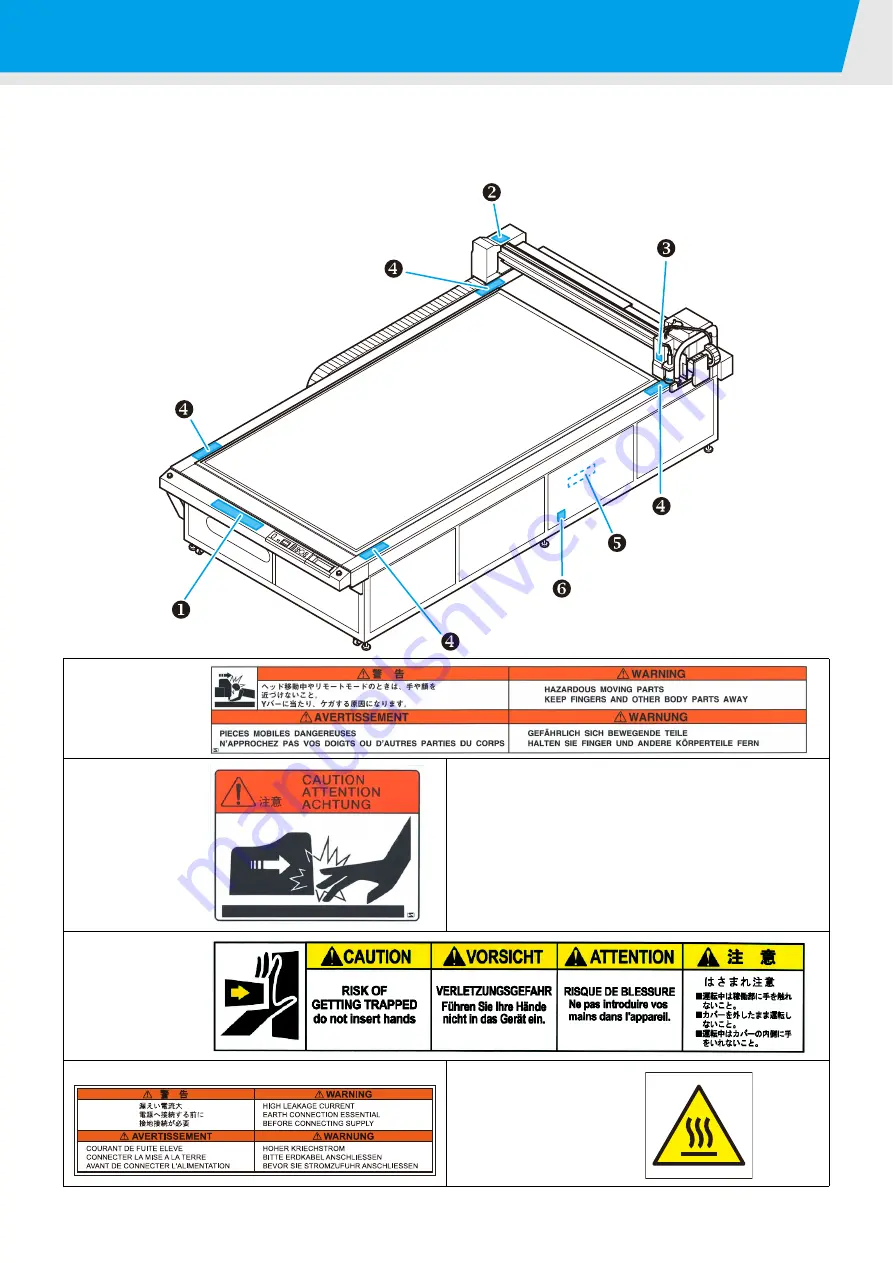
Warning labels

Warning labels are stuck on the printer body. Be sure to fully understand the warning given on the labels.
If a warning label is illegible due to stains or has come off, purchase a new one from your local distributor or
our office.

X

Order No.M902663

Y

Order No.M902667

Z

Order No.M905694

[

Order No.M905672

\

Order No.M905624

]

Order No.M903239

Содержание CF3-1610

Страница 1: ...ON MANUAL FLAT BED CUTTING PLOTTER MIMAKI ENGINEERING CO LTD TKB Gotenyama Building Kitashinagawa Shinagawa ku Tokyo 141 0001 Japan Phone 81 3 5420 8671 Fax 81 3 5420 8687 URL http www mimaki co jp D201768 14 ...

Страница 2: ...ng the Blower Signal Cable 1 10 Connecting the Interface Cable 1 10 Turning the Power ON OFF 1 11 Turning the Power ON 1 11 Turning the Power OFF 1 11 Emergency Stop 1 12 Applying an Emergency Stop 1 12 Resetting an Emergency Stop 1 12 Compressed Air Connection 1 13 Checking the Compressed Air Pressure 1 13 Dust Collector Connections 1 14 Precautions for Dust Collector Connections 1 14 Connecting ...

Страница 3: ...r Specifications 1 40 Setting Automatic Head Retraction 1 41 Setting the Vacuum 1 42 Enabling Disabling the Vacuum Automatic OFF Function 1 42 Chpater 2 Basic Operations Basic Operation Workflow 2 2 Moving the Head 2 3 Moving the Head Using the Head Retraction VIEW Function 2 3 Moving the Head Using the Jog Keys 2 4 Fixing the Workpiece 2 5 Fixing the Workpiece with Adhesive Tape 2 5 Fixing the Wo...

Страница 4: ...3 Making the Most of the Unit Assigning Pen Numbers 3 2 Cutting the Same Data Again Copy 3 4 Setting Multi pass Cutting 3 5 Setting Multi pass Cutting Models R1 TF2 3 5 Setting Multi pass Cutting Model M 3 7 One Stroke Setting 3 8 Rotating Coordinate Axes ROTATE 3 9 Setting the Cutter Stroke 3 10 Setting the Displayed Units 3 11 Swivel Blade Dummy Cut 3 12 Setting Axis Alignment 3 13 Setting the D...

Страница 5: ...r Marks 4 10 Using the Light Pointer to Check the Workpiece Tilt 4 10 Register Mark Detection Procedure 4 11 Continuous Cutting of Register Marks 4 12 Clearing the Register Mark Offsets 4 13 Chapter 5 Daily Maintenance Daily Maintenance 5 2 Cutting Panel Surface 5 2 Covers 5 2 Unit B 5 3 Cleaning the Blower Filter 5 4 Cleaning the Dust Collector Brush 5 5 Maintaining the Dust Collector Hose when U...

Страница 6: ...nt 6 14 Tool lifts up the paper 6 15 Drawn lines are broken or smudged 6 15 No reciprocating movement 6 15 Spindle motor does not rotate 6 16 Runout of the end mill 6 16 Abnormal noise or vibration during rotation 6 16 Dust collector does not work 6 16 Problems Causing an Error Display 6 17 Non fatal Errors 6 17 Fatal Errors 6 19 Errors Displayed on the Spindle Controller 6 20 Self Test 6 21 Condu...

Страница 7: ...vi ...

Страница 8: ...ay cause harmful interference to radio communications Operation of this equipment in a residential area is likely to cause harmful interference in which case the user will be required to correct the interference at his own expense In the case where MIMAKI recommended cable is not used for connection of this device limits provided by FCC rules can be exceeded To prevent this use of MIMAKI recommend...

Страница 9: ...representative if you discover any problems in the manual We reserve the right to change this manual at any time without notice If this manual becomes unreadable due to fire or other damage contact your Mimaki representative to purchase a new copy Accessories The accessories differ according to the type of head and the target application Confirm the accessories supplied against the separate ACCESS...

Страница 10: ...e notes thoroughly to operate the machine properly Useful information is given with this symbol Refer to the information to operate the machine properly Indicates the reference page for related contents The symbol indicates that the instructions must be observed as strictly as the CAUTION instructions including DANGER and WARNING instructions A sign representing a precaution the sign shown at left...

Страница 11: ...rk is prohibited To prevent electrical shock be sure to set OFF the main power circuit breaker and disconnect the power plug before carrying out maintenance For some units capacitors may take one minute for discharging therefore start maintenance work three minutes after setting OFF the main power circuit breaker and disconnecting the power plug Be sure to carry out grounding work to prevent elect...

Страница 12: ...se if you require movement of the unit please contact to our service engineer CAUTION A place exposed to direct sunlight A place that vibrates Do not install the device at a place where the temperature of the cut panel surface exceeds 60 C The cut panel can deform or break down The device will fail to give correct results if installed in a place that vibrates A place in which temperature and humid...

Страница 13: ...ion The page title Function outlines using text and illustrations Indicates the model to which the current page is applicable Number of an operation sequence Shows buttons in text surrounded by Indicates a screen display Gives hints and precautions about operation Page number Section 1 Page 41 ...

Страница 14: ... fully understand the warning given on the labels If a warning label is illegible due to stains or has come off purchase a new one from your local distributor or our office XOrder No M902663 YOrder No M902667 ZOrder No M905694 Order No M905672 Order No M905624 Order No M903239 ...

Страница 15: ...ring the Cutting Panel 1 16 Attach the felt mat Models R1 M 1 16 Inserting the Work Guide Plates 1 16 Blades and Workpieces 1 17 Workpiece Types that Can be Cut by Each Model Guide 1 17 Blade Types that Can Be Used in Each Model 1 17 Mounting Tools 1 18 Mounting the Pen or Swivel Blade 1 19 Mounting the Tangential Cutter 1 22 Mounting the Grid Roller 1 24 Mounting the Reciprocating Cutter 1 25 Mou...

Страница 16: ... may result in nausea due to exhaust fumes from the blower A ceiling height of at least 2300 mm above the floor is required Model Width Depth Height Total weight CF3 1631 2250 mm 4120 mm 1320 mm Approx 1050 kg CF3 1610 2250 mm 1860 mm 1320 mm Approx 600 kg This unit cannot be installed by the customer Its installation should be entrusted to our service personnel or your electrical contractor Be su...

Страница 17: ...ected 5 Work guide plates Guides for mounting the workpiece P 1 16 6 Blower Unit option Provides vacuum adhesion of the workpiece on the cutting panel 7 Adjustable feet Adjust the leg height to maintain the cutting panel surface horizontal 8 Operation panel Makes the settings required for the unit P 1 8 9 EMERGENCY switch Press in the event of an emergency The power is forcibly cut to stop unit op...

Страница 18: ...s tube fuse P 6 28 7 USB interface USB 2 0 interface connector P 1 10 8 Blower signal connector Connects to the interior of the electrical box 9 Option connector Connector to handle special applications 10 Service inlet Inlet to supply power to the dust collector P 1 14 Select the socket according to the power supply specification used 11 Power switch for the service socket Turns the power supply ...

Страница 19: ...r positioning to read register marks and setting the origin position 4 Unit B Mounts the reciprocating cutter holder 5 Register mark sensor Sensor to detect register marks 6 Unit C Mounts a grid roller or cutter holder P 1 24 Name Function 1 Warning lamp Lights when the reciprocating cutter is oscillating 2 Height adjustment dial Adjusts the height of the head 3 Height adjustment bar Adjusts the h...

Страница 20: ...ter Used for positioning to read register marks and setting the origin position 4 Unit B Mounts the low pressure cutter 5 Register mark sensor Sensor to detect register marks 6 Unit C Mounts a grid roller or high pressure cutter Name Function 1 Height adjustment dial Adjusts the height of the head 2 Height adjustment bar Adjusts the head height according to the thickness of the workpiece 1 2 3 4 5...

Страница 21: ...adjust the head height 5 Register mark sensor Sensor to detect register marks 6 Spindle fixing screws Fix the spindle to the head P 1 27 7 Dust collector Sucks in the dust produced by cutting 8 Light pointer Used for positioning to read register marks and setting the origin position 9 Auxiliary air duster Blows dust from the heads and operation panel Name Function 1 Warning lamp Lights when the sp...

Страница 22: ... the unit status and setup menus PAGE keys Displays the next or previous page FUNCTION keys Select functions on the local menu and set values CE key Cancels a selection clears data copying etc or reverts to the previous level without saving entered values END key Saves the entered values ORIGIN key Sets the drawing ORIGIN point on the unit cutting area REMOTE LOCAL key Switches the unit between th...

Страница 23: ... located on the left side of the unit Check the condition from the viewing window of the left side cover SPEED DOWN UP RUN WARNING ERROR E3000C Displays the code number and error description when the spindle motor is in warning status or error status Lamp lights to warn the operator before a spindle motor error occurs Lights when the spindle is operating Lamp lights when the spindle motor is in er...

Страница 24: ... power before connecting the blower signal cable RS 232C interface cable or USB interface cable Failure to turn off the power may result in electric shocks or damage to the unit Connection work at the distribution board is required to provide the power supply for this unit The customer cannot connect the unit power cable Contact your Mimaki representative to arrange for connection of the power cab...

Страница 25: ... PC 2 Press the POWER OFF switch The unit turns off after POWER DOWN WAIT is displayed and the POWER lamp goes out Checking Uncut Data While the power is ON do not place objects other than the workpiece on the cutting panel When the power is turned ON the head moves to the upper right retraction point The head may be damaged if it hits an object Wait at least 30 seconds after turning OFF the power...

Страница 26: ...nit Applying an Emergency Stop 1 Press the EMERGENCY switch Operation stops and the unit turns off Resetting an Emergency Stop 1 Turn the EMERGENCY switch clockwise to unlock it 2 Press the POWER ON switch Unit operation starts Wait at least 30 seconds after turning OFF the power before resetting an emergency stop Failure to do so may result in unit malfunctions ...

Страница 27: ...essure if the pressure display does not indicate 0 33 MPa After checking press Drain Bleed When oil or water collects in the regulator it bleeds automatically You are recommended to spread a towel under the regulator A compressor and air hoses are required to connect the compressed air supply The compressor and air hoses are not available as options They should be provided by the customer Use air ...

Страница 28: ...vailable for dust collector connections 100 V and 200 V Make the connection that matches the voltage of the dust collector that is being connected The voltage from the power cable for dust collection cannot be automatically converted and output to the voltage of the connected dust collector Be certain to connect a dust collector that matches the power supply voltage Connection of a dust collector ...

Страница 29: ... 2 Connect the dust collector power cable and turn ON the switch Go to the rear of the unit and plug the power cable into the service socket 3 Insert the dust collector plug into the dust collector socket 4 Turn ON the dust collector 5 Press 6 Press and select VACUUM Vacuum adhesion starts The dust collector operation starts as vacuum adhesion starts Dust collector hose Dust collector Connect the ...

Страница 30: ...model that you will be using Use of the incorrect type will result in the protrusion of the felt mat retainer and this may hit the head When a felt mat is put down on the cutting board with M model use felt mat retainer B When not using a felt mat remove the felt mat retainer not to hit a head When the work guide plate is mounted be sure to adjust the head height and then turn the power on not to ...

Страница 31: ...board Reflective sheet Paternhaport Sandblasted rubber Paternhaport Various types of workpiece may exist with the same name Use the workpiece types in the table above as a guideline only Always make a test cut before cutting actual workpieces P 2 22 Tool Cutter Type Model TF2 Model R1 Model M A B C A B C Cutter High speed 30 Carbide 30 Titanium coated 30 High speed 45 Carbide 45 Titanium coated 45...

Страница 32: ...e Tools See page Model TF2 A Pen swivel blade P 1 19 B Low pressure tangential cutter P 1 22 C High pressure tangential cutter P 1 22 Grid roller P 1 24 Model R1 A Pen swivel blade P 1 19 B Low pressure tangential cutter P 1 22 Reciprocating cutter P 1 25 C Grid roller P 1 24 High pressure tangential cutter P 1 22 Model M Milling P 1 27 ...

Страница 33: ...w counterclockwise to loosen it Open out Holder A 2 Insert a ball point pen holder or swivel blade holder into Unit A Align the flange on the ball point pen holder or swivel blade holder with the groove in Holder A 3 Tighten the Unit A screw Close Holder A and tighten the screw clockwise Correct quality may not be achieved if the screw is not fully tightened Screw Holder A Flange Groove in Holder ...

Страница 34: ... to remove Holder B from Holder A 3 Insert the blade with the tweezers 4 Turn the adjusting knob clockwise to insert Holder B into Holder A 5 Tighten the lock nut Turn the lock nut clockwise to tighten it Handle the blade carefully to avoid injury For safety handle the blade with the tweezers supplied Lock nut Holder A Holder B Adjustin g knob ...

Страница 35: ...that the blade protrudes For details about the adjustment see P 2 20 Replacing the Swivel Blade 1 Mounting the Swivel Blade Follow steps 1 5 to replace the blade 2 Adjust the amount that the blade protrudes For details about the adjustment see P 2 20 ...

Страница 36: ... loosen it 2 Insert the blade Insert the blade using the tweezers supplied Insert the blade into the holder keeping it in the direction shown in the diagram 3 Tighten the cutter stopper Turn the cutter stopper clockwise to tighten it Do not touch the blade with bare hands This may cause injury When mounting an NT high speed blade use the hand lapper supplied to round off the tip and grind down the...

Страница 37: ...g the Cutter Holder After mounting the cutter mount the cutter holder into the unit 1 Loosen the cutter holder stopper screw Turn the stopper screw counterclockwise to loosen it 2 Insert the Unit B pin into the groove in the cutter holder 3 Use the screwdriver supplied to tighten the stopper screw Firmly fasten the cutter holder Correct quality may not be achieved if the stopper screw is not fully...

Страница 38: ...ng the Head Height 1 Loosen the grid roller stopper screw Turn the stopper screw counterclockwise to loosen it 2 Insert the Unit C pin into the groove in the grid roller 3 Use the screwdriver supplied to tighten the stopper screw Firmly fasten the cutter holder Correct quality may not be achieved if the stopper screw is not fully tightened Stopper screw Align the pin and groove ...

Страница 39: ...ossible into the cutter holder For safety handle the blade with the tweezers supplied Be sure to orient the blade correctly 2 Use the 2 0 mm Allen key supplied to tighten the set screw and clamp the blade A reciprocating cutter holder is required to mount the reciprocating cutter For Unit B Model R1 Name Cutter Holder 07 SPA 0114 Blade Carbide 17 SPB 0065 20 mm blade SPB 0055 Short Long Allen key ...

Страница 40: ...rew Turn the fixing screw counterclockwise to loosen it The fixing screw is 3 mm long It will fall out of Unit B if it is loosened too much 4 Tighten the fixing screw Push the cutter holder firmly upwards to eliminate any clearance between the lug on Unit B and the groove in the reciprocating holder and then tighten the fixing screw Firmly fasten the cutter holder If the holder is loose the cutter...

Страница 41: ... Select an appropriate end mill for the operation Also select suitable machining conditions You are recommended to select an end mill shaft diameter with a tolerance of with respect to the chuck nominal diameter A shaft diameter with a tolerance of can be mounted However using a shaft not meeting these recommended tolerances may result in problems of runout or inadequate holding force Before start...

Страница 42: ...l out the spindle motor 3 Provide a pedestal to use for replacing the end mill Positioning the pedestal with the end mill toward you makes replacement easier 4 Place the spindle motor on the pedestal Align the spindle motor groove with the mounting position on the pedestal 5 Loosen the chuck nut Turn the chuck nut counterclockwise with the 14 mm wrench supplied Groove Counter clockwise Pull out Pe...

Страница 43: ...ut clockwise with the 14 mm wrench supplied 8 Return the spindle motor to its original position and tighten the locking lever 1 Insert the spindle motor with the stopper aligned with the groove on the unit 2 Turn the spindle motor to lock it 3 Turn the locking lever clockwise When mounting the end mill with φ6 of the blade in the condition of 1 refer to P 2 12 Setting the Cutting Conditions and de...

Страница 44: ...ovement becomes harder after about one turn Turn it further to release it 3 Replace the end mill Pull out the used end mill and mount the new end mill as described in step 6 of Mounting the Milling Tool End Mill 4 Tighten the chuck nut and return the spindle motor to its original position 1 Insert the spindle motor with the stopper aligned with the groove on the unit 2 Turn the spindle motor to lo...

Страница 45: ...Turn the wrench until the chuck nut is removed from the spindle 3 Remove the end mill from the chuck 3 Remove the chuck from the chuck nut As shown in the diagram to the right tilt the chuck in the direction of the wrench flats and remove it If the chuck cannot be removed tilt it once more in the direction of the other wrench flats and remove it 4 Mount the new chuck Tilt the chuck in the directio...

Страница 46: ... when a function is selected by pressing a function key on the Main Menu Use the function keys to enter the set values The displayed to the left of a set value indicates the currently enabled value Sub menu 2 Function execution screen This is the screen to execute functions Includes test cut data clear and automatic communication condition evaluation functions LOCAL 3 5 I NTERFACE MODE SET SEL F T...

Страница 47: ...do not appear when the grid roller is selected Pen Selected This remote screen appears when HEAD A TOOL Pen is selected for TOOL SELECT in the local menu Swivel Blade Selected This remote screen appears when HEAD A or TOOL SWIVEL is selected for TOOL SELECT in the local menu Milling Head Attached This remote screen appears when the milling head is attached REMOTE 0KB TANGENT I AL BLD S 3 0 P1 5 0 ...

Страница 48: ...he mark indicates the current set value 5 Press Display the second page of INTERFACE The unit will automatically recognize its interface to the PC The interface to the PC that first received the data is recognized and the selection is cancelled with the Data Clear operation P 2 34 Item Set value BAUD RATE 1200 2400 4800 9600 19200 bps DATA BITS 7 8 bit PARITY NON ODD EVEN STOP BITS 1 2 bit HANDSHA...

Страница 49: ...s The settings are saved Press if you do not want to save the settings USB Connection Setting the communication conditions for a USB connection to the PC 1 Select INTERFACE Conduct steps 1 and 2 of P 1 34 RS 232C Connection 2 Press and select USB 3 Press and select MACHINE No 00 99 4 Press The settings are saved Press if you do not want to save the settings Item Set value MACHINE No 00 99 I NTERFA...

Страница 50: ...select the CMD SW set value Enable Disable 5 Press The settings are saved Press if you do not want to save the settings Item Set value Enable Give priority to commands received from the PC Ignore settings from the plotter operation panel Disable Ignore settings received from the computer and give priority to settings from the plotter operation panel LOCAL 3 5 I NTERFACE MODE SET SEL F TEST MODE SE...

Страница 51: ... Display the fourth page of the MODE SET menu Press several times 4 Press and select the OH UNIT set value Set values INITVal SETVal 5 Press The settings are saved Press if you do not want to save the settings Item Set value INIT Val Return the maximum effective cutting area of the unit SET Val Return the value set for the cutting area in the local menu P 2 29 LOCAL 3 5 I NTERFACE MODE SET SEL F T...

Страница 52: ...ess and select MODE SET 3 Display the fourth page of the MODE SET menu Press several times 4 Press and select the ORIGIN set value Set values LOWRIGHT CENTER 5 Press The settings are saved Press if you do not want to save the settings Item Set value LOWRIGHT Lower right of the maximum effective cutting area CENTER Center of the maximum effective cutting area LOCAL 3 5 I NTERFACE MODE SET SEL F TES...

Страница 53: ...es 2 Press and select MODE SET 3 Display the fourth page of the MODE SET menu Press several times 4 Press and select the GDP set value Set values 0 025 mm 0 010 mm 5 Press The settings are saved Press if you do not want to save the settings 1 GDP Graphic Display Pitch Item Set value 0 025 mm Sets the GDP to 0 025 mm 0 010 mm Sets the GDP to 0 010 mm LOCAL 3 5 I NTERFACE MODE SET SEL F TEST MODE SE...

Страница 54: ... l o t t e r S p e c i f i c a t i o n s This unit uses the command MGL IIC3 Set the CAD command to connect to the unit to MGL IIC3 Only the MGL IIC3 commands are available in MODE SET This command cannot be changed at the plotter ...

Страница 55: ... 1s 2s 5 Press The settings are saved Press if you do not want to save the settings Item Set value OFF No automatic retraction 1 s Head moves to the retraction position one second after cutting drawing is complete 3 s Head moves to the retraction position three seconds after cutting drawing is complete The head always automatically returns to the retraction position after cutting drawing or copyin...

Страница 56: ...he vacuum cannot turn off automatically if automatic head retraction is OFF ON If automatic head retraction is set to 1 s or 3 s the vacuum turns off automatically after head retraction OFF Vacuum remains on after head retraction REV DRIVE ON Press to select the blower operation adhesion release OFF Press to start vacuum adhesion The optional blower is required to use the vacuum functions Regardle...

Страница 57: ...del TF2 2 8 Setting the Z axis Origin for Model M 2 9 Setting the Cutting Conditions 2 12 Set Items 2 14 Adjusting the Blade to Match the Workpiece 2 18 Adjusting the Tangential Cutter 2 18 Adjusting the Swivel Blade 2 20 Adjusting the Head Height 2 21 Making a Test Cut 2 22 Checking the Tool Status 2 23 Checking the Status Between Tools 2 26 Setting the Cutting Area 2 29 Setting the Drawing Origi...

Страница 58: ...ols For Model R1 or TF2 See Selecting Tools for Model R1 and Model TF2 P 2 8 For Model M See Setting the Z axis Origin for Model M P 2 9 4 Setting the Cutting Conditions See Setting the Cutting Conditions P 2 12 5 Making a Test Cut See Making a Test Cut P 2 22 6 Setting the Cutting Area See Setting the Cutting Area P 2 29 7 Setting the Drawing Origin See Setting the Drawing Origin P 2 31 8 Cutting...

Страница 59: ... destination point Move to the upper right head full retraction position for CF3 1631 Move to the upper left head retraction position Move to the upper right head retraction position Move to the lower left head retraction position Move to the lower right head retraction position 4 Press The head retracts to the designated position If Automatic Head Retraction P 1 41 is set the head automatically r...

Страница 60: ...tus Any page from page 1 to page 4 can be open 2 Press a jog key once The head move mode is selected The light pointer moves to the tool tip position The light pointer coordinates are displayed 3 Press a jog key to move the head The destination coordinates are displayed To change the head travel speed Press 4 Press or The tool tip moves to the light pointer position and the display at Step 1 reapp...

Страница 61: ... rubber use adhesive tape to fasten the workpiece Fix the four edges of the workpiece with the adhesive tape The following table shows the acceptable workpiece thicknesses Four area stickers are stuck on the table They indicate the maximum effective cutting area Mount the workpiece inside this area The plotter is unable to cut outside the area indicated by the area stickers Use an adhesive tape th...

Страница 62: ...ts if REV DRIVE in Setting the Vacuum P 1 42 is set OFF The operations from Step 4 are not required If REV DRIVE in Setting the Vacuum P 1 42 is set ON proceed to Step 4 4 Press and select VACUUM Vacuum operation starts 5 Press The optional blower is required to use the vacuum function If the workpiece is too small to cover all the air holes on the cutting panel use some sort of sheet to cover all...

Страница 63: ...rea F1 Vacuum applied to area R2 Vacuum applied to area F2 Vacuum applied to area F3 Vacuum applied to area F4 Align the workpiece with the origin position marks in the four corners Vacuum Valves Opening and closing vacuum valves Origin position mark In the four corners of the table Marks Use as guides for opening or closing the valves Marks are also provided on the unit front panel For Model CF3 ...

Страница 64: ...s several times 2 Press and select TOOL SELECT 3 Press and select Unit Set values A B C 4 Press and select TOOL The selectable tools differ according to the type of head Tools Available for Each Type of Head 5 Press The settings are saved Press if you do not want to save the settings Tools Available for Each Type of Head Tools cannot be selected for Model M LOCAL 1 5 TOOL SELECT COND I T I ON TEST...

Страница 65: ...lue that the felt mat is slightly cut Adjusted amount of cutting based on the Z axis origin 3 0 to 3 0mm Always reset the Z axis origin after changing the head height Using the unit without resetting the Z axis origin can damage the unit if the end mill is pushed through the cutting panel for example Side view of unit Workpiece Felt mat Cutting board Z ORIGIN Press the key and set the position of ...

Страница 66: ...eys 4 Press The set origin coordinates are saved Press if you do not want to save the settings The Z axis origin cannot be set for Model R1 or Model TF2 The rotational speed and descent speed settings are not saved This origin coordinate setting is cleared when the power is turned off Setting the Z axis origin will disable the setting of the Z cutting position via command LOCAL 1 5 Z OR I G I N CO...

Страница 67: ...cond page Origin Offset setting screen is displayed 4 Press to set the offset value Set values 3 0 3 0 mm 5 Press The set offset value is saved Press if you do not want to save the settings LOCAL 1 5 Z OR I G I N COND I T I ON TEST CUT Z OR I G I N 1 2 M I L L I NG START M I L L s p d 5 0 0 0 r pm Z 0 0mm 5mm s Z OR I G I N 2 2 OR G O F F S E T 0 0 Z OR I G I N 2 2 OR G O F F S E T 0 3 ...

Страница 68: ...settings are complete press The setting is saved Press if you do not want to save the setting The set cutting conditions apply to the tool set in Selecting Tools P 2 8 For Model R1 or TF2 If the approximation type is set to Arc in the FineCut plotter settings an excessive load may be applied to the cutter and damage the cutter tip when cutting some media If Arc is set adjust the FineCut cutting co...

Страница 69: ... OFFSET E OFFSET UP ANGLE REC CUTTER RING DIS PRESS COR VIBRATION REC CUTTER R5 SPD R10 SPD R15 SPD R θ CUTTER X SPEED PRESSURE ACCELE R θ CUTTER X F OFFSET E OFFSET UP ANGLE R θ CUTTER X RING DIS PRESS COR RESERVE R θ CUTTER X R5 SPD R10 SPD R15 SPD ROLLER X SPEED PRESSURE ACCELE ROLLER X UP ANGLE RING DIS PRESS COR ROLLER X Y PRESS RESERVE RESERVE SWIVEL SPEED PRESSURE OFFSET SWIVEL ACCELE RESER...

Страница 70: ...0 1cm s 3 0 10 step 1cm s 10 0 50 step 5cm s PRESSURE 20 100 step 5g 100 400 step 10g 300 1500 step 100g 2 2 Available only when the VIBRATION cutting condition is set OFF if cutter holder 2N is mounted Unit B in Model R1 500 1500 step 100g Fixed 1500g in setting VIBRATION 1000 5000 step 100g ACCELE 0 1 0 5 step 0 1G F OFFSET 0 2 50 step 0 05mm E OFFSET 0 2 50 step 0 05mm UP ANGLE 0 45 step 1 RING...

Страница 71: ...g the cutting crease direction This reduces the degree of damage to the workpiece by the tool Sets the rounding radius R and adds a line segment between segments for a consecutive series of line segments This reduces the degree of damage to the workpiece by the tool Corrects the tool downwards pressure when cutting crease cutting a thick workpiece Applying the PRESS COR value to the previously set...

Страница 72: ...1 2 3 4 5 10 15 cm s R30 SPEED OFF 1 2 3 4 5 10 15 20 cm s R40 SPEED OFF 1 2 3 4 5 10 15 20 25 cm s R50 SPEED OFF 1 2 3 4 5 10 15 20 25 30 cm s R100 SPEED OFF 1 2 3 4 5 10 15 20 25 30 cm s Z SPEED 1 100 step 1mm s ROUND SPEED 5000 60000 rpm MEDIA HEIGHT 0 1 55 0 mm Z ORIGIN POSITION Workpiece Type End Mill Cut Count Acryl Sumitomo Chemical SUMIPEX 3t SPB 0074 For details about the end mill the bla...

Страница 73: ...usly set speed is used for drawing Speed for drawing an arc with a radius at least 40 mm but less than 50 mm If OFF the previously set speed is used for drawing Speed for drawing an arc with a radius at least 50 mm but less than 100 mm If OFF the previously set speed is used for drawing Descent speed for the milling tool Rotation speed rpm of the milling tool Designates the thickness of the mounte...

Страница 74: ... the tweezers supplied Special tangential cutter blades and holders are available to suit different workpieces Contact your dealer or an office of MIMAKI for details Head Type Cutter Holder Cutter Applicable Workpiece R1 Unit B Cutter holder 2 N For high speed 30 For carbide 30 Workpiece thickness 2 mm max Cutter holder 07 For 20 mm blade For carbide 17 Corrugated cardboard Unit C Crease roller CN...

Страница 75: ...s a rule of thumb the blade tip should protrude by workpiece thickness 0 2 mm 3 Tighten the dial stopper while pushing the dial in the direction of the arrow The dial has some play To eliminate discrepancies in the amount that the blade protrudes push the dial in the direction of the arrow while tightening the dial stopper When mounting a tangential cutter in Unit B set the VIBRATION cutting condi...

Страница 76: ...etails 1 Loosen the lock nut Turn the lock nut counterclockwise to loosen it 2 Turn the adjusting knob to adjust the amount that the blade protrudes The blade tip enters the holder when the adjusting knob is turned clockwise As a rule of thumb the blade tip should protrude by workpiece thickness base paper thickness 2 3 Tighten the lock nut while ensuring that the adjusting knob does not turn Turn...

Страница 77: ...height adjustment dial to lower the head while holding down the height adjustment bar Lower the head until the bottom edge of the height adjustment bar touches the workpiece surface 4 Tighten the fixing screws alternately starting from the bottom Turn the fixing screws clockwise to lock the head When raising the head support the head base by hand Attempting to raise the head with the height adjust...

Страница 78: ...isplay the first page 4 Press TEST CUT is selected 5 Press The test cut starts Press to cancel the test cut and return to Step 2 No Check Item Check Point 1 Are the cutting drawing conditions suitable Work is correcly cut or drawing is not smudged 2 Is tool mounted eccentrically An eccentric tool can cause displacement in the cutting or drawing 3 Do tools match When a tangential cutter cuts over a...

Страница 79: ...FFSET value too low in cutting conditions Increase the E OFFSET P 2 12 Blade is mounted eccentrically Conduct Adjust Eccentricity in tool adjustments P 6 6 Lines displaced at Point A Abnormal angle θ of tangential cutter Conduct Adjust θ in tool adjustments P 6 8 Cutting incomplete Press value low Increase the PRESSURE in the cutting conditions P 2 12 Cutting incomplete at corners The F OFFSET and...

Страница 80: ...ase roller for coated board Crease lines torn along flutes of corrugate cardboard Y PRESS value in the cutting conditions is too high Align the corrugated cardboard flutes in the Y axis direction Decrease the Y PRESS in the cutting conditions P 2 12 Check Point Cause Remedy See page Broken lines Swivel cutter incorrectly mounted Fully tighten the holder screw P 1 19 Speed is too slow Increase the ...

Страница 81: ... Replace the end mill P 1 30 Inappropriate end mill for the workpiece being cut Use an end mill suitable for the workpiece P 1 30 The set cutting conditions do not suit the end mill or workpiece Review the cutting conditions P 2 12 Test cut pattern drawn by Model M The test pattern drawn for the milling tool differs from the one drawn by Model TF2 or Model R1 The up cut and down cut are conducted ...

Страница 82: ... items requiring adjustment The description below refers to the pen and tangential cutter For the crease roller read tangential cutter as crease roller Overview The tangential cutter is displaced with respect to the center of the pen regardless of the direction of movement Remedy Adjust the Offset in Adjust Cutter in tool adjustments P 6 3 Overview The cut is rotated clockwise or counterclockwise ...

Страница 83: ... of the direction of movement Remedy Adjust Pattern B for Adjust Eccentricity in Adjust Cutter in tool adjustments P 6 3 Overview The cut is rotated clockwise or counterclockwise and the cutting start point is too far forward or backward Remedy See the remedies described for Sample B and Sample C Overview The cut is rotated clockwise or counterclockwise and the tangential cutter is displaced to th...

Страница 84: ...utting end point is too long or too short and the tangential cutter is displaced to the right or left Remedy See the remedies described for Sample D and Sample E Overview The cut is rotated clockwise or counterclockwise the cutting end point is too long or too short and the tangential cutter is displaced to the right or left Remedy See the remedies described for Sample B Sample D and Sample E Samp...

Страница 85: ...rrently set lower right LR point The coordinates are displayed with respect to the command origin position 5 Align the light pointer with the lower right corner of the required cutting area Press the jog keys to move the light pointer to the lower right corner LR of the cutting area that you wish to set If necessary change the head travel speed To change the head travel speed press To clear the se...

Страница 86: ...lign the light pointer with the upper right corner of the required cutting area Press the jog keys to move the light pointer to the upper left UL corner of the cutting area that you wish to set If necessary change the head travel speed To change the head travel speed press 9 Press The UR point is saved Press if you do not want to save the settings AREA L R 4 5 0 0 3 0 0 0 SPEED FAST CUT AREA UPPER...

Страница 87: ...e you wish to set the origin Move the light pointer to the tool tip to display the current light pointer coordinates To change the head travel speed press 3 Press The origin is set The tool tip moves to the light pointer position The origin is set as coordinate position 0 0 When the head is moved by pressing the jog keys the screen displays the coordinates with respect to the origin The Sample Cut...

Страница 88: ...oad data from the host computer Cutting starts automatically after the data is received When cutting is complete the display appears as shown to the right 3 Press 4 Press select REVERSE and remove the workpiece Once the workpiece has been removed press and stop the blowing air Model Name X axis mm Y axis mm CF3 1610 1000 1600 CF3 1631 3100 1600 X axis Y axis Maximum effective cutting area Origin s...

Страница 89: ... unit operation After a while unit operation stops and it enters the local status The time when operation stops depends on the data being processed Processing a circle Stops when the circle is complete Other line segments Stops when processing of each vector is complete Restarting Processing 1 Press The unit enters remote status and processing restarts Functions that Can Be Set After Interrupting ...

Страница 90: ...the SINGLE COPY function 4 To cut using a PC that is different from the PC that sent the cutting data the previous time 1 Set local status If the unit is in remote status press to set local status Press during data processing to interrupt the processing 2 Display the second page of the local menu Press several times 3 Press DATA CLEAR is selected 4 Press The data is cleared Press to cancel the dat...

Страница 91: ...2 3 5 Setting Multi pass Cutting Model M 3 7 One Stroke Setting 3 8 Rotating Coordinate Axes ROTATE 3 9 Setting the Cutter Stroke 3 10 Setting the Displayed Units 3 11 Swivel Blade Dummy Cut 3 12 Setting Axis Alignment 3 13 Setting the Displayed Language DISPLAY 3 14 Setting NR Head Retraction 3 15 Setting the Close Time 3 16 Manual Cutting 3 17 Cleaning the Table 3 18 Chapter 3 Making the Most of...

Страница 92: ...MODE SET is selected 3 Display the fifth page of the MODE SET menu Press several times 4 Press PEN ASSIGN is selected 5 Press to change HEAD from B to A Set values A B C 6 Press and select TOOL to PEN The set values differ according to the mounted tools 7 Press to display the PEN 2 setup menu 8 Press to change HEAD from A to B Set values A B C LOCAL 3 5 I NTERFACE MODE SET SEL F TEST MODE SET 1 7 ...

Страница 93: ...ress and select TOOL to Θ CUTTER1 The set values differ according to the mounted tools To set Pens 3 to 6 repeat the procedure from Step 7 10 Press The settings are saved Press if you do not want to save the settings PEN ASS I GN 2 6 PEN2 HEAD B TOOL θ CUTTER1 ...

Страница 94: ...ng at the same position 5 Press to display the second page of the local menu 6 Press and select SINGLE COPY 7 Press to copy the data Press to cancel the copy When copying is complete the display reverts to the screen at Step 5 after the head retraction To cut once more repeat the procedure from Step 4 Use DATA CLEAR to clear P 2 34 the receive buffer before receiving the data to be copied If the d...

Страница 95: ...e Set Item Set value Description CUT START OFF 5 15 30 45 60 s Set the cut start time that sets the delimiter between data Multi pass cutting starts if the next data is not received within the set time PRESS 1st OFF 300 g to 5000 g 1 50 g steps 1 The set values differ according to the unit Unit B 300 g to 1500 g Unit C 1000 g to 5000 g except grid roller Sets the press value for the first cut PRES...

Страница 96: ...ets the fifth press value 8 Press The press value settings are saved Press if you do not want to save the settings To use FineCut to output data set OFF at Step 4 and set multi pass cutting in the FineCut output settings MUL T I PASS 2 2 PRESS 3 r d OFF PRESS 4 t h OFF PRESS 5 t h OFF MUL T I PASS 2 2 PRESS 3 r d 7 0 0 g PRESS 4 t h 9 0 0 g PRESS 5 t h 1 0 0 0 g ...

Страница 97: ...6 Press to save the setting Press if you do not want to save the setting Set the cut start time that sets the delimiter between data Multi pass cutting starts if the next data is not received within the set time Set Item Set value Description CUT START OFF 5 15 30 45 60 s Set the cut start time that sets the delimiter between data Multi pass cutting starts if the next data is not received within t...

Страница 98: ...s if you do not want to save the setting Set value Description OFF No one stroke cutting ON One stroke cutting SORT One stroke cutting starting from the point near the tool This function is only available if MARK SENSOR is set OFF To use FineCut to output data set OFF at Step 4 and set one stroke cutting Sort in the FineCut output settings Cutting start point Cutting direction LOCAL 3 5 I NTERFACE...

Страница 99: ...ct the ROTATE set value Set values 90 90 5 Press to save the setting Press if you do not want to save the setting Set value Description 90 Sets the coordinate axes at the lower right corner of the maximum effective cutting area 90 Sets the coordinate axes at the lower left corner of the maximum effective cutting area Command origin set at lower right corner Set rotated by 90 LOCAL 3 5 I NTERFACE M...

Страница 100: ...and select MODE SET 3 Press and select the Z STROKE set value Set values 7 mm 4 mm When milling the setting values will be 8 mm and 3 mm 4 Press to save the setting Press if you do not want to save the setting Set value Description 7mm 8mm 1 1 Setting value when milling Tool rises 7 mm 8mm 1 above the workpiece surface 4mm 3mm 1 Tool rises 4 mm 3mm 1 above the workpiece surface LOCAL 3 5 I NTERFAC...

Страница 101: ... of the MODE SET menu Press several times 4 Press and select the UNIT set value Set values mm inch 5 Press to save the setting Press if you do not want to save the setting Set value Description mm Displays millimeters inch Displays inches LOCAL 3 5 I NTERFACE MODE SET SEL F TEST MODE SET 1 7 Z STROKE 7mm MUL T I PASS VACUUM MODE SET 5 7 PEN ASS I GN DRAW LVL NORMAL UN I T mm MODE SET 5 7 PEN ASS I...

Страница 102: ...T 3 Display the second page of the MODE SET menu Press several times 4 Press and select the DUMMY CUT set value Set values OFF ON 5 Press to save the setting Press if you do not want to save the setting Set value Description OFF Makes no dummy cut ON Makes a dummy cut Maximum effective cutting area X axis Y axis LOCAL 3 5 I NTERFACE MODE SET SEL F TEST MODE SET 1 7 Z STROKE 7mm MUL T I PASS VACUUM...

Страница 103: ...grid on the workpiece P 2 31 3 Display the fourth page of the local menu Press several times 4 Press and select AXIS ALIGN 5 Align the light pointer with the right edge point A of the grid Press the jog keys to move the light pointer to the right edge of the grid The head travel speed can be changed during head movement Change speed 6 Press to save Point A Press if you do not want to save the sett...

Страница 104: ...nu Press several times 3 Press and select MODE SET 4 Display the sixth page of the MODE SET menu Press several times 5 Press and select DISPLAY Set values JPN ENG 6 Press to save the setting Press if you do not want to save the setting LOCAL 1 5 TOOL SELECT COND I T I ON TEST CUT LOCAL 3 5 I NTERFACE MODE SET SEL F TEST MODE SET 1 7 Z STROKE 7mm MUL T I PASS VACUUM MODE SET 6 7 MARK SENSOR RESERVE...

Страница 105: ...the MODE SET menu Press several times 5 Press and select the set value Set value Enable Disable 6 Press to save the setting Press if you do not want to save the setting Set value Description Enable Head retracts when the NR command is received Disable Head does not retract when the NR command is received LOCAL 1 5 TOOL SELECT COND I T I ON TEST CUT LOCAL 3 5 I NTERFACE MODE SET SEL F TEST MODE SET...

Страница 106: ...es 5 Press and select the set value Set values OFF 5 s 30 s 6 Press to save the setting Press if you do not want to save the setting Set value Description OFF Do not clear data automatically Conduct the procedure in P 2 34 to DATA CLEAR 5 s to 30 s Data is automatically cleared when the set time elapses after cutting drawing is complete LOCAL 1 5 TOOL SELECT COND I T I ON TEST CUT LOCAL 3 5 I NTER...

Страница 107: ...Press several times 3 Press and select Manual CUT 4 Press to move Tool The tool travel speed and the tool height can be changed during tool movement To change the speed Press AUTO MID SLOW FAST MAX To raise or lower the tool Press UP DOWN 5 Press when manual cutting is complete LOCAL 1 5 TOOL SELECT COND I T I ON TEST CUT LOCAL 4 5 CUT AREA AX I S AL I GN MANUAL CUT MOVE mm 3 1 1 0 0 0 0 SPEED AUT...

Страница 108: ... 5 Press to start cleaning Press to cancel cleaning Adjusting the Brush Table cleaning may be ineffective when cutting a thick workpiece or if the head is raised In this case lower the brush position before cleaning 1 Loosen the dial A The brush ascends LOCAL 1 5 Z OR I G I N COND I T I ON TEST CUT LOCAL 5 5 RESERVE RESERVE DUST SWEEP DUST SWEEP SWEEP AREA 1 8 END KEY t o START CE KEY t o CANCEL D...

Страница 109: ...al A Pushing down the brush positioning rod while turning the dial A allows the brush to drop lower than the head at some times 4 Clean the table Clean the table by conducting the procedures described to the left 5 When cleaning is complete loosen the dial A 6 Push down the brush positioning rod and tighten the dial A within the cutting range Take care not to overtighten the dial A Tighten it such...

Страница 110: ...3 20 ...

Страница 111: ... to Register Mark Separation and Register Mark Size 4 6 Register Mark Colors 4 7 Bleeding or Smudging of Register Marks 4 7 Setting Register Mark Detection 4 8 Precautions Related to Register Mark Detection 4 8 Setting Register Mark Detection 4 9 Detecting Register Marks 4 10 Using the Light Pointer to Check the Workpiece Tilt 4 10 Register Mark Detection Procedure 4 11 Continuous Cutting of Regis...

Страница 112: ...ks with respect to the data The register marks described here are used to detect the work orientation and the lengths of the X and Y axes They are not crop marks Square register marks Set a side length of the register mark between 5 mm and 30 mm Single register marks Set a side length of the register mark between 5 mm and 30 mm Use a register mark line thickness between 0 2 mm and 0 5 mm Double re...

Страница 113: ... Reading Functions Permitted Arrangements of Register Marks and the Design The TP1 start position must be 10 mm min from the left edge of the workpiece and 30 mm min from the maximum effective cutting area Square register marks Single register marks Double register marks ...

Страница 114: ... register marks causes displacement of the cutting position Square register marks Single register marks Double register marks Valid drawing area 10 mm Prohibited drawing areas blue areas 10 mm Square register mark Register mark origin Square register mark size 5 mm 30 mm Prohibited drawing areas blue areas Single register marks 2 x register mark size 2 x register mark size Double register marks 2 ...

Страница 115: ...and therefore of the cutting position False Detection of Register Marks Example 2 Square register marks TP3 of Pattern A and TP1 of Pattern C TP2 of Pattern A and TP1 of Pattern B are not separated by at least 10 mm Therefore when using offset printing print the register marks on only one of the four CMYK plates such as printing register marks as K100 Printing the register marks on one plate only ...

Страница 116: ...n A and register mark size B The register marks may not be detected correctly if the register mark size B is too small with respect to the register mark separation A Create register marks of an appropriate size Square register marks Single register marks Double register marks A 200 mm max 500 mm 1000 mm 1500 mm min B 10 mm 15 mm 20 mm 30 mm Prohibited drawing area Prohibited drawing area Separate ...

Страница 117: ... in advance that the register mark color can be read If the workpiece surface has a high gloss or a hairline pattern or if it has some background colors register marks may not be correctly Bleeding or Smudging of Register Marks Bleeding or smudging of the register marks may result in incorrect detection of the register mark origin and displaced cutting Recommended Black register marks White regist...

Страница 118: ...iece direction 3 pt Detects TP1 TP2 and TP3 Conducts tilt correction and scale correction in the workpiece direction and Y direction 4 pt Detects TP1 TP2 TP3 and TP4 Conducts tilt correction and 4 point scale correction SIZE 5 mm 30 mm Sets a side length of the register mark edge length STYLE Square Single Double Select from three register mark styles X COPY 1 99 This is effective for multiple ide...

Страница 119: ...s 7 Set X COPY Y COPY and SCALE P 4 8 Table of Settings X COPY Press to set Y COPY Press to set SCALE Press to set 8 Press to save the settings Press if you do not want to save the settings When setting STYLE to Double at Step 5 set SIZE to 10mm or more If 10mm or less register mark could not be detected LOCAL 3 5 I NTERFACE MODE SET SEL F TEST MODE SET 1 7 Z STROKE 7mm MUL T I PASS VACUUM MODE SE...

Страница 120: ...de is selected By pressing the jog keys to move the light pointer between points TP1 and TP2 the tilt of the workpiece can be checked from the light pointer line Adjust the tilt of the workpiece to this line If the workpiece has curled flatten it out If using cutting software that does not offer register mark functions ensure that the areas between TP1 and TP3 and between TP1 and TP2 are free of i...

Страница 121: ...pears if the register marks cannot be detected Mount the workpiece again 5 After the register marks are detected the SCALE CORRECT screen appears This example shows 4 point detection If the data lengths and detected lengths differ use to set them 6 Press after setting The local mode is selected If SCALE is set to before register mark detection starts Press to disable the scale correction If SCALE ...

Страница 122: ...g 3 Detect the register marks P 4 10 Copying starts when register mark detection is complete Repeat Step 2 and Step 3 for the designated number of cuts 4 When the designated number of workpieces has been cut the head automatically retracts and the system reverts to local mode When data remains in the receive buffer the remaining data will also be cut Be sure to carry out the Data Clear operation b...

Страница 123: ...cal mode If the unit is in remote status press to set local status Press during data processing to interrupt the processing 2 Display the second page of the local menu Press several times 3 Press and select DATA CLEAR 4 Press to conduct SCALE CLEAR Press to cancel the SCALE CLEAR and return to Step 2 The display reverts to the local menu after the offsets are cleared LOCAL 1 5 TOOL SELECT COND I T...

Страница 124: ...4 14 ...

Страница 125: ... the Dust Collector Brush 5 5 Maintaining the Dust Collector Hose when Using M Head 5 5 Cleaning the Milling Tool End Mill 5 5 Cleaning with Auxiliary Air 5 6 Cleaning the Photoelectric Sensors and Register Mark Sensor 5 6 Replacing the Head with an Optional Head 5 7 Replacing a Model R1 or TF2 Head with a Model M Head 5 8 Replacing a Model M Head with a Model R1 or TF2 Head 5 9 Chapter 5 Daily Ma...

Страница 126: ...wer outlet If the surface is lightly contaminated wipe off the dirt with a clean dry cloth For more severe dirt wipe off the dirt with a small amount of alcohol on a clean dry cloth Covers If the surface is lightly contaminated wipe off the dirt with a clean dry cloth For more severe dirt wipe off the dirt with a small amount of alcohol on a clean dry cloth Do not use an abrasive cleaner or thinne...

Страница 127: ...enance Unit B The reciprocating shaft in Model R1 may cease moving if lubrication is inadequate Before starting work wipe the surface with a clean dry cloth Then apply a small amount of the supplied grease to the shaft with a brush Shaft ...

Страница 128: ... 1 Loosen the eight screws and slide the cover in the direction of the arrows 2 Remove the cover 2 Remove the lid Disengage the hooks and remove the lid 3 Remove the filter 4 Use a vaccum cleaner to suck dust and dirt from the filter 5 Put the filter back in its original position 1 Push in the filter and firmly close the lid The hooks will not engage unless the lid is firmly closed 2 Engage the ho...

Страница 129: ...ust collector brush so that it bends down Maintaining the Dust Collector Hose when Using M Head The suction force drops off if the dust collector hose is blocked 1 Disconnect the hose joints and clean the dust collector hose The hose joints are located at the positions shown in the diagram below 2 Reconnect the hose joints in their original positions Cleaning the Milling Tool End Mill Clean all di...

Страница 130: ...a cleaner hose Connect the cleaner hose to the quick connector and to the black dial at the right of the head Due to the effects of the air the cleaner hose may fly around if it is disconnected while air is flowing Turn off the air flow before releasing or disconnecting the hose The hose can be dangerous if it enters your eye Before connecting the cleaner hose to the quick connector check that an ...

Страница 131: ...CF 1610 Part Name Part No M R1 TF2 M R1 TF2 Model M OPT C0209 Felt mat SPC 0530 6 6 2 2 Felt mat retainer A SPC 0519 10 10 6 6 Felt mat retainer B SPC 0520 10 6 Model TF2 OPT C0210 Cutting board SPC 0521 2 SPC 0522 1 SPC 0523 1 Felt mat retainer B SPC 0520 10 6 Model R1 OPT C0211 Cutting board SPC 0521 2 SPC 0522 1 SPC 0523 1 Felt mat SPC 0518 3 3 1 1 Felt mat retainer B SPC 0520 10 10 6 6 Felt ma...

Страница 132: ...ails about attaching the head 4 Attach the Model M Head 1 Check that the head fixing screws are horizontal 2 Support the Model M head at Part A shown in the diagram 3 Align the screw holes in the unit with the screw holes in the head 4 Mount the head Engage the Holes C at the rear of the head with the Lugs B on the unit If it is difficult to engage the lugs in the holes move the head from side to ...

Страница 133: ...ount the dust collector hose Replacing a Model M Head with a Model R1 or TF2 Head 1 Disconnect the motor cable connector from the spindle motor and apply the cap to the connector 1 Turn the connector several times clockwise 2 Remove the connector 3 Attach the protective cap to the connector 2 Trap the motor cable connector in the fixing spring assembly on the right of the head Trap the end of the ...

Страница 134: ... at Step 4 onto the head stand for storage See Step 6 for details about attaching the head 6 Mount the Model R1 or TF2 head 1 Check that the head fixing screws are horizontal 2 Support the head at Part A shown in the diagram 3 Align the screw holes in the unit with the screw holes in the head 4 Mount the head Engage the Holes C at the rear of the head with the Lugs B on the unit If it is difficult...

Страница 135: ...he CAD data is sent 6 14 An error occurs when the data is sent 6 14 Tool lifts up the paper 6 15 Drawn lines are broken or smudged 6 15 No reciprocating movement 6 15 Spindle motor does not rotate 6 16 Runout of the end mill 6 16 Abnormal noise or vibration during rotation 6 16 Dust collector does not work 6 16 Problems Causing an Error Display 6 17 Non fatal Errors 6 17 Fatal Errors 6 19 Errors D...

Страница 136: ...cutter ascends P 2 12 Setting the Cutting Conditions Circle start and end points do not match A circle start and end points can be displaced due to the workpiece thickness and hardness Use circle θ correction to correct for the displacement Grid lines torn along flutes of corrugate cardboard Tearing can occur if the press value in the cutting conditions is too high when grid cutting along the flut...

Страница 137: ...r Adjusts the cutter mounted in Head B or C The following adjustments are available to adjust the cutter For more efficient cutter adjustment follow the sequence below ZDXDYDXDYDZ This sequence is one recommended example Set in a sequence that will be convenient for you A roller can be adjusted in the same way XAdjust Eccentricity P 6 6 Make this adjustment after replacing the blade or the tool YA...

Страница 138: ...ead containing a roller was selected at Step 3 ROLLER X ROLLER Y are displayed in the second and third lines 5 Press the jog keys to move the head to the drawing position 6 Press to start drawing the test pattern 7 Check and adjust the test pattern Press or to make the adjustments CUTTER X ROLLER X 33 0 41 0 33 0 41 0 CUTTER Y ROLLERY 41 0 49 0 86 0 94 0 For details see P 6 5 Adjusting the Offsets...

Страница 139: ...the operation panel ADJ CENTER 3 3 CUTTER X 3 6 4 0 CUTTER Y 4 5 4 0 TEST PATTERN Distance from pen to cutter roller with respect to the X axis Press or to adjust 0 05 mm pitch Distance from pen to cutter roller with respect to the Y axis Press or to adjust 0 05 mm pitch X axis Y axis When a drawing by the cutter is displaced to the right dotted line 1 Press to set the Set value Current indicated ...

Страница 140: ...ove the head to the drawing position 5 Press to start drawing the test pattern 6 Check and adjust the test pattern Press or to make the adjustments A LENGTH 4 4 Set values 4 4 For details see P 6 7 Adjusting the Eccentricity First mount a pen in Unit A 20mm 20mm Normal patternA Normal patternB 20mm 20mm Normal patternA Normal patternB Test pattern drawn by the cutter Test pattern drawn by the roll...

Страница 141: ...the adjustment Adjusting Pattern A Adjusting Pattern B When using the 2 carbide reciprocating cutter adjust the horizontal line to protrude approx 2 mm ADJ CENTER 1 3 A LENG 0 0 0 0 B 0 0 0 0 TEST PATTERN Adjusting Pattern A Aligns the center of the cutter roller with the center of the holder Press or to adjust 0 05 mm pitch Adjusting Pattern B Adjustment to check whether the tool is tilted Press ...

Страница 142: ...p 3 ROLLER θ is displayed in the second line 5 Press the jog keys to move the head to the drawing position If a head containing a roller was selected at Step 3 proceed to Step 7 6 Press and select Pattern 1 or Pattern 2 Two adjustment test patterns are available for a cutter Pattern 1 and Pattern 2 Values in parentheses in the diagram show the sizes of Pattern 2 First mount a pen in Unit A 30 200 ...

Страница 143: ...play the adjustment screen Offset Adjustment Operations from Step 4 on P 6 4 Adjust Eccentricity Operations from Step 4 on P 6 6 Press to exit without saving the adjusted values Adjusting the θ Angle The θ angle can be adjusted on the screen below 1 Check the displacement between the patterns drawn with the pen and cutter roller 2 Make the adjustment Rotated clockwise Rotated counterclockwise ADJ ...

Страница 144: ...s 2 Press and select TOOL ADJUST 3 Press and select CIRCLE θ 4 Press or and select the head to set 5 Press several times to display the fourth page of the menu 6 Press and select Enable 7 Press The setting is saved Press if you do not want to save the settings LOCAL 5 5 RESERVE RESERVE TOOL ADJUST TOOL ADJUST 1 2 B CUTTER ADJUST C ROL LER ADJUST C I RCLE θ COR C I RCLE θ 1 1 B HEAD C HEAD C I RCLE...

Страница 145: ...od 7 Press several times to display the second page of the menu 8 Press to start drawing the test pattern Draw the 10 R 20 and 20 R 50 test patterns Circle type for correction Radius R 5 mm 20 mm Radius R 50mm 5 mm Radius R 10mm 50 mm Radius R 100mm 10 mm Radius R 20mm 100 mm Radius R In some cases this cannot be corrected by the CAD system First set arc θ correction to Enable If arc θ correction ...

Страница 146: ... and R 100 test patterns 12 Check and adjust the test pattern Press or to make the adjustments Set values 9 8 9 8 For details see Circle θ Correction Method at the bottom of the page 13 Press to save the adjusted values Press if you do not want to save the settings Circle θ Correction Method End point displaced inward End point displaced outward C I RCLE θ 3 4 5 0 R 1 0 0 0 0 R 1 0 0 0 0 TEST PATT...

Страница 147: ...the light pointer to the center of the cross pattern Adjust the light pointer position if it is not aligned with the center of the pattern drawn by the pen Moving the light pointer in the X axis direction Move up Press 3 to 3 mm Move down Press 3 to 3 mm Moving the light pointer in the Y axis direction Move right Press 3 to 3 mm Move left Press 3 to 3 mm 7 Press to save the adjusted values Press i...

Страница 148: ...the EMERGENCY switch pressed in Release the EMERGENCY switch P 1 12 Is the area sensor responding Remove whatever is located between the sensor and the head P 1 3 Is the unit in local status Set to remote status P 1 32 Is the interface cable connected properly Correctly connect the interface cable P 1 10 Has the interface been changed Perform the Data Clear operation P 2 34 Do the communications c...

Страница 149: ...move up and down normally Is the Unit A screw loose Re tighten the Unit A screw P 2 18 Is the drawing speed too high Decrease the SPEED in the cutting conditions P 2 12 Is the drawing pressure too low Increase the PRESSURE in the cutting conditions P 2 12 Is the pen out of ink Replace the pen with a new one P 1 19 Inadequate lubrication of the reciprocating shaft Apply a small amount of grease to ...

Страница 150: ...tative Is dirt trapped inside the chuck or spindle Clean out the chuck and spindle P 1 31 Is the chuck mounted correctly Mount the chuck correctly P 1 31 The ball bearings could be worn Contact your Mimaki representative Is the end mill bent Replace the end mill Could be caused by foreign matter or wear in the ball bearings Contact your Mimaki representative Is power supplied to the dust collector...

Страница 151: ...g was interrupted Do not make illegal key operations An ASCII dump was made with an effective area less than A3 Set the effective area to at least A3 size before conducting an ASCII dump An ASCII dump was made with the origin set at a position that does not allow an effective area of A3 to be obtained ERROR 31 NO DATA The copy function was used with no data received Before using the copy function ...

Страница 152: ... The head is not mounted Mount the head ERROR 85 AIR PRESS Low cooling air pressure supplied to the Model M head Cutting operation continues Check the compressor Check the air hoses ERROR 86 MILL LOAD Excessive load applied during milling operation with Model M head Cutting operation continues Change the cutting conditions P 2 12 Replace the end mill ERROR 87 MILL WARM The controller detected an a...

Страница 153: ...Model M head θ is displayed as Z ERROR 02 MAIN RAM ERROR 42 X OVERCURRENT ERROR 71 θ OVERCURRENT 2 2 ERROR 70 θ OVERCURRENT can occur if the head is too high or if θ rotation occurs when the Head B tool has not reached the workpiece Contact your dealer or an office of MIMAKI if ERROR 70 θ OVERCURRENTD re occurs after lowering the tool to contact the workpiece and retransmitting the data If using t...

Страница 154: ...r Wait a while and turn it back on E3 The motor cable connector is disconnected or the sensor is defective Check the motor cable connector Turn off the plotter Wait a while and turn it back on E4 Unit internal temperature is abnormally high E5 Circuit error E6 Motor was constrained and rotation stopped at least 3 s Turn off the plotter and remove the constraint Wait a while and turn the plotter ba...

Страница 155: ...parel industry The outer lines are cut after drawing the inner lines DATA DUMP P 6 24 The unit draws the data sent from the PC as ASCII code to check for abnormalities SAMPLE 0 5 mm Use this to make a paper container sample from thick paper approx 0 5 mm thick The perimeter is cut after cutting the grid Requires thick paper at least A4 in size SAMPLE1 0 mm Use this to make a paper container sample...

Страница 156: ... 2 Display the third page of the local menu Press several times 3 Press and select SELF TEST Pen No Model R1 Model TF2 1 Head B B Tool Reciprocating cutter 1 Cutter 1 2 Head C C Tool Roller 1 Roller 1 3 Head B B Tool Reciprocating cutter 2 Cutter 1 4 Head C C Tool Roller 1 Roller 1 5 Head A A Tool Swivel blade Swivel blade 6 Head A A Tool Pen Pen LOCAL 3 5 I NTERFACE MODE SET SEL F TEST SEL F TEST...

Страница 157: ...d PARAMETER DUMP see P 6 24 and P 6 26 respectively 5 Press to draw the data Press to cancel SELF TEST SEL F TEST 1 5 PATTERN CUT 1 PATTERN CUT 2 DATA DUMP SEL F TEST 2 5 SAMPLE 0 5mm SAMPLE 1 0mm SAMPLE 1 5mm SEL F TEST 3 5 C I RCLE R 3 C I RCLE R 5 C I RCLE R 1 0 SEL F TEST 4 5 C I RCLE R 2 0 C I RCLE R 5 0 C I RCLE R 1 0 0 SEL F TEST 5 5 PARAMETER DUMP RESERVE RESERVE ...

Страница 158: ...e pen tip is not located at the upper left corner of the paper align the upper left corner of the paper with the pen 9 Press to make the DATA DUMP The unit draws the communications conditions An DATA DUMP is not possible for Model M The ASCII dump requires a pen and A3 or larger paper If paper smaller than A3 is used the drawing may extend outside the paper When ASCII dump is set the tool automati...

Страница 159: ...Self Test 6 25 6 Troubleshooting 10 Send data from the PC The unit draws the ASCII code data To quit press Wait a while and conduct DATA CLEAR P 2 34 ...

Страница 160: ...he upper left corner of the paper If the pen tip is not located at the upper left corner of the paper align the upper left corner of the paper with the pen A PARAMETER DUMP is not possible for Model M The parameter dump requires a pen and A3 or larger paper If paper smaller than A3 is used the drawing may extend outside the paper When parameter dump is set the tool automatically changes to pen Ens...

Страница 161: ...Self Test 6 27 6 Troubleshooting 9 Press to make the parameter dump The unit starts drawing the parameters To quit press Wait a while and DATA CLEAR P 2 34 ...

Страница 162: ... Replace with a supplied fuse Replacement fuse ET1A time lag low breaking capacity rating 1A 250 V AC 4 Attach the cap to the fuse holder Turn the cap clockwise while pushing it in Fuse replacement is only required if the external I O terminals are used For normal use without the external I O terminals replacement of the fuse is not necessary Replace the fuse if the plotter stops operating when an...

Страница 163: ...kw can be set up to two for CF3 1610 The blower is an option It is not attached to the main body Maximum cut work thickness M model 50 mm R1 model 20 mm TF2 model 10 mm Maximum set work thickness M model 50 mm R1 model 20 mm TF2 model 25 mm Settable work weight 120 kg max No point load 60 kg max No point load Receiving buffer capacity 1 MB Command MGL IIc3 MGL IIc supported 3 3 This is a dedicated...

Страница 164: ...6 30 ...

Страница 165: ...D201768 14 29062009 ...

Страница 166: ...NH FW 3 30 Printed in Japan MIMAKI ENGINEERING CO LTD 2009 ...

Отзывы: