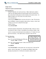


Chuck
Top View
o
Pressure switch and
digital gauge.
o
Manual actuators
o
Pressure adjustment
knob.
Tailstock
o
Pressure adjustment
knob.
o
Manual actuator
o
Pressure switch and
digital gauge.
Hydraulic Pressure
The pressure regulators are factory set to 200psi. Each regulator should be adjusted
according to specific job requirements.
Pressure Adjustment
Pressure adjustments are made using the adjustment knobs shown above, where a larger
number represents higher pressure, and a lower number represents lower pressure.
Manual Actuation
The valves can be actuated manually by pressing the buttons shown above and on the
preceding page.
Switches/Digital Pressure Gauges
The pressure switches are factory set to trip just below the factory set pressure of 200 psi.
When pressure adjustments are made, the pressure switches must be adjusted
accordingly. Note that the display shows the pressure or trip point / 10 (Example 200 psi
is displayed as 20).
Pressure Switch Adjustment
The trip level is adjusted by pressing the SET key – the display will flash:
o
Then press UP or DOWN, causing the rightmost digit to flash.
o
Press UP or DOWN to adjust the rightmost digit.
o
Press SET, the middle digit will flash.
o
Press UP or DOWN to adjust the middle digit.
o
Press and hold the SET key to store the data.
o
Press SET twice more to display the pressure reading.
46
Содержание ML Series
Страница 2: ......
Страница 4: ......
Страница 6: ......
Страница 20: ......
Страница 23: ...CHAPTER 2 SPECIFICATION ML14 26 Series Machine Layout 17 ...
Страница 24: ...ML35 40 Series Machine Layouts ML35 Series ML40 Series 18 ...
Страница 33: ...CHAPTER 3 SITE PREPARATION 27 ML22 ML26 Lifting device drawing ...
Страница 34: ......
Страница 74: ......
Страница 76: ......
Страница 78: ......
Страница 80: ......
Страница 82: ......
Страница 83: ......