background image

OM-223 Page 14

2-3. Tipping

Y

Be careful when placing or

moving unit over uneven

surfaces.

2-4. 115 VAC Receptacle And Circuit Breakers

Ref. ST-800 452-A

Y

Turn Off power before con-

necting to receptacle.

1

115 V 15 A AC Receptacle

RC9

Power is shared between RC9 and

Remote 14 receptacle RC8 or

terminal strip 1T (see Section 2-8).
2

Circuit Breaker CB1

3

Circuit Breaker CB2

CB1 protects 115 volts ac portion of

RC8, 1T, and RC9 from overload.
CB2 protects 24 volts ac portion of

RC8 and 1T from overload.
Press button to reset breaker.

1

3

2

Содержание Auto Deltaweld 452

Страница 1: ... Load Output 50 or 60 Hz Three Phase Model Welding Output Range DC OCV DC Rating 200 V 230 V 380 V 400 V 440 V 460 V 575 V KVA KW 300 Amp 300 A 32 29 Volts DC 100 Duty Cycle 10 32 38 43 21M 42 3 2 27 1 8 25 1 7 23 1 6 21 1 6 17 1 3 16 9 1 26 12 9 0 21 450 Amp 450 A 38 36 5 Volts DC 100 Duty Cycle 10 38 48 21M 72 3 2 63 2 7 39 2 6 37 2 2 33 2 1 32 1 4 25 1 1 25 1 1 09 21 1 0 26 650 Amp 650 A 44 Vol...

Страница 2: ......

Страница 3: ...C Machinery Directives 89 392 EEC 91 368 EEC 93 C 133 04 93 68 EEC Standards Safety Requirements for Arc Welding Equipment part 1 EN 60974 1 1990 Arc Welding Equipment Part 1 Welding Power Sources IEC 974 1 April 1995 Draft revision Degrees of Protection provided by Enclosures IP code IEC 529 1989 Insulation coordination for equipment within low voltage systems Part 1 Principles requirements and t...

Страница 4: ......

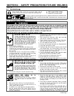
Страница 5: ... to your health 2 1 Keep your head out of the fumes 2 2 Use forced ventilation or local exhaust to remove the fumes 2 3 Use ventilating fan to remove fumes 3 Welding sparks can cause explosion or fire 3 1 Keep flammables away from welding Do not weld near flammables 3 2 Welding sparks can cause fires Have a fire extinguisher nearby and have a watchperson ready to use it 3 3 Do not weld on drums or...

Страница 6: ...s shown on inside label double check all connections jumper link positions and input voltage before applying power S 179 290 1 4 5 ÍÍÍ ÍÍÍ ÍÍÍ 3 ÍÍÍ ÍÍÍ 2 V A V 3 1 96 S 179 563 1 Warning Watch Out There are possible hazards as shown by the symbols 2 Electric shock from wiring and exposed weld terminals can kill 3 Close door before turning on unit 1 2 3 1 96 1 Warning Watch Out There are possible ...

Страница 7: ...OM 223 Page 11 1 2 Manufacturer s Rating Labels For CE Products S 174 346 S 174 347 S 174 348 Match label to one on unit See Section 2 1 ...

Страница 8: ...tance Weld Output Terminal Positive Low Inductance Weld Output Terminal Negative Weld Output Terminal Input V Volts Off Wire Feed Protective Earth Ground U0 Rated No Load Voltage Average U1 Primary Voltage U2 Conventional Load Voltage Line Connection I1 Primary Current I2 Rated Welding Current X Duty Cycle Three Phase Transformer Rectifier IP Degree Of Protection Alternating Current S1 KVA Direct ...

Страница 9: ...sconnect Device Locate unit near correct input pow er supply Y Special installation may be required where gasoline or volatile liquids are present see NEC Article 511 or CEC Section 20 3 6 18 in 460 mm 18 in 460 mm OR 1 2 Movement Location And Airflow 4 5 2 2 Dimensions And Weights Dimensions Dimensions Height 27 1 4 in 692 mm C D Width 22 1 4 in 565 mm D E Depth 35 3 4 in 908 mm 4 Holes A 35 in 8...

Страница 10: ...r before con necting to receptacle 1 115 V 15 A AC Receptacle RC9 Power is shared between RC9 and Remote 14 receptacle RC8 or terminal strip 1T see Section 2 8 2 Circuit Breaker CB1 3 Circuit Breaker CB2 CB1 protects 115 volts ac portion of RC8 1T and RC9 from overload CB2 protects 24 volts ac portion of RC8 and 1T from overload Press button to reset breaker 1 3 2 ...

Страница 11: ...ance Positive Low Inductance 700 4 0 2 2 0 2 3 0 2 4 0 3 3 0 3 4 0 3 4 0 4 4 0 Inductance 800 4 0 2 2 0 2 3 0 2 4 0 3 4 0 3 4 0 4 4 0 4 4 0 Weld cable size AWG is based on either a 4 volts or less drop or a current density of at least 300 circular mils per ampere S 0007 D 2 6 Electrical Service Guide 60 Hertz Models 300 Amp Model 450 Amp Model 650 Amp Model Input Voltage 230 460 575 200 230 460 57...

Страница 12: ...it common for 24 and 115 volts ac circuits REMOTE POWER ON OFF L To remote On Off switch REMOTE POWER ON OFF M To remote On Off switch REMOTE VOLTAGE SENSING N Voltage sensing signal from Negative weld output terminal REMOTE VOLTAGE SENSING P Voltage sensing signal from Positive weld output terminal Not Used 3 2 4 C REMOTE OUTPUT CONTROL 115 VAC 24VAC REMOTE REMOTE VOLTAGE SENSE GND REMOTE POWER O...

Страница 13: ... Section 2 6 4 Line Disconnect Device See Section 2 6 5 Reed Switch Ground Current Sensor Optional 6 Grounding Conductor If unit is equipped with optional ground cur rent sensor route grounding conductor through reed switch two times and connect to ground terminal Close access door 3 8 in 3 8 in IMPORTANT GND 3 PE Connect GND PE Conductor First Input Contactor L1 U L2 V L3 W GND PE Earth Ground L1...

Страница 14: ...down Light 5 Remote Voltage Control Switch For front panel control place switch in Panel position For remote control place switch in Remote position and connect remote de vice see Section 2 8 6 Output Switch For front panel control of output place switch in Panel position For remote control of out put place switch in Remote position and connect remote device see Section 2 8 Y Turn Off power before...

Страница 15: ...l Reduce amperage or duty cycle before welding Y Exceeding duty cycle can damage unit and void war ranty Overheating 0 15 V OR Reduce Duty Cycle Minutes duty1 4 95 SA 168 918 100 Duty Cycle SECTION 4 MAINTENANCE TROUBLESHOOTING 4 1 Routine Maintenance Y Disconnect power before maintaining 3 Months Replace Unreadable Labels Clean And Tighten Weld Terminals Repair Or Replace Cracked Weld Cable 6 Mon...

Страница 16: ...n fan on If using wire feeder place Output Contactor switch in Remote 14 position and connect wire feeder see Sections 2 7 and 2 8 If feeder is not being used place switch in On position see Section 3 1 Check repair or replace feeder see wire feeder Owner s Manual Unit overheated Allow unit to cool with fan On see Section 3 2 Have Factory Authorized Service Agent check control board PC1 Unit provi...

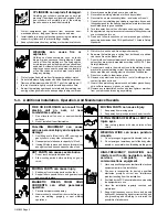
Страница 17: ...ed undersized or poorly spliced cables 11 Do not drape cables over your body 12 If earth grounding of the workpiece is required ground it directly with a separate cable do not use work clamp or work cable 13 Do not touch electrode if you are in contact with the work ground or another electrode from a different machine 14 Use only well maintained equipment Repair or replace damaged parts at once Ma...

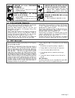
Страница 18: ...nt from traveling long possibly unknown paths and causing electric shock and fire hazards 9 Do not use welder to thaw frozen pipes 10 Remove stick electrode from holder or cut off welding wire at contact tip when not in use 11 Wear oil free protective garments such as leather gloves heavy shirt cuffless trousers high shoes and a cap 12 Remove any combustibles such as a butane lighter or matches fr...

Страница 19: ...nada M9W 1R3 Safe Practices For Occupation And Educational Eye And Face Protection ANSI Standard Z87 1 from American National Standards Institute 1430 Broadway New York NY 10018 Cutting And Welding Processes NFPA Standard 51B from National Fire Protection Association Batterymarch Park Quincy MA 02269 5 5 EMF Information ConsiderationsAbout Welding And The Effects Of Low Frequency Electric And Magn...

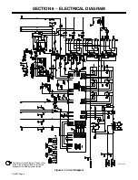
Страница 20: ...OM 223 Page 4 SECTION 6 ELECTRICAL DIAGRAM SC 181 304 For Primary Circuit Diagram Portion refer to the Circuit Diagram located inside the wrapper of the welding power source Figure 6 1 Circuit Diagram ...

Страница 21: ...OM 223 Page 5 NOTES ...

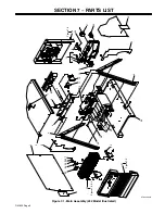
Страница 22: ...ION 7 PARTS LIST 1 ST 800 992 B 26 27 2 3 4 5 6 7 8 9 10 13 14 15 16 17 18 19 20 21 23 24 25 28 29 30 31 32 23 3 4 Figure 7 3 4 Figure 7 2 Figure 7 5 11 12 22 33 34 35 36 37 Figure 7 1 Main Assembly 452 Model Illustrated ...

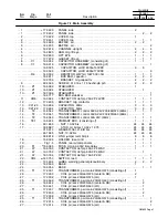
Страница 23: ...00 230 460 60Hz 1 14 T2 159 043 TRANSFORMER control 50A 24V 50Hz 1 1 1 15 TE1 159 244 PRIMARY BOX consisting of 1 1 1 16 601 835 NUT 10 32 brs 24 24 24 17 038 887 STUD pri bd brs 10 32 x 1 375 24 24 24 010 913 WASHER flat 218 ID brs 24 24 24 601 835 NUT 10 32 brs 24 24 24 038 618 LINK jumper term bd pri 8 8 8 18 159 034 HOLDER fuse mintr 1 1 1 19 Fig 7 5 PANEL rear w components 1 1 1 20 F1 156 065...

Страница 24: ...3 4 29 605 538 CABLE TIE 0 4 500 bundle 3 3 4 30 161 294 BRACKET mtg rectifier 2 2 2 31 Fig 7 2 PANEL front w components 1 1 1 32 SR1 175 070 RECTIFIER si diode Fig 7 3 1 32 SR1 175 071 RECTIFIER SCR main Fig 7 4 1 32 SR1 175 072 RECTIFIER SCR main Fig 7 4 1 33 Shunt 166 368 SHUNT meter 50mV 650A 1 1 1 PLG14 130 204 CONNECTOR SOCKETS consisting of 1 1 1 114 066 CONNECTOR rect skt 20 14ga 3 3 3 RC1...

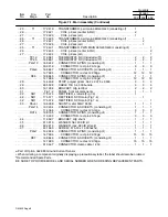
Страница 25: ... 22 18ga 10 10 10 PLG5 152 249 CONNECTOR SOCKETS consisting of 1 1 1 147 995 CONNECTOR rect skt 22 18ga 15 15 15 3 CR3 006 393 RELAY encl 24VAC DPDT 1 1 1 4 CR5 006 393 RELAY encl 24VAC DPDT 1 1 1 5 CB1 2 093 995 CIRCUIT BREAKER man reset 1P 15A 250VAC 2 2 2 6 RC9 604 176 RECEPTACLE str dx grd 2P3W 15A 125V 1 1 1 7 163 855 CONNECTOR CAPACITOR w leads consisting of 1 1 1 RC8 143 976 CONNECTOR SOCKE...

Страница 26: ...utput 1 1 1 25 160 935 CLIP spring 3 3 3 26 601 835 NUT 10 32 brs 2 2 2 010 913 WASHER flat 218 ID x 460 OD x 031thk brs 1 1 1 27 038 887 STUD pri bd brs 10 32 x 1 375 1 1 1 28 S3 4 011 609 SWITCH tgl SPDT 15A 125VAC 2 2 2 29 R1 035 897 POTENTIOMETER CP std slot 1 T 2W 1K ohm 1 1 1 30 CR1 134 163 RELAY encl 24 120VAC DPDT 1 1 1 31 PC2 178 130 CIRCUIT CARD digital meter 1 31 PC2 177 909 CIRCUIT CAR...

Страница 27: ...re 7 4 Rectifier SCR Main SR1 452 652 Model 1 2 3 4 5 6 7 ST 800 696 A Description Part No Dia Mkgs SR1 Item No Figure 7 4 Rectifier SCR Main 452 652 Model Fig 7 1 Item 32 Quantity 175 071 175 072 1 C7 12 048 420 CAPACITOR cer disc 01uf 1000VDC 6 6 2 176 168 BAR mtg rectifier 2 2 3 166 667 CLAMP spring thyristor rectifier 5 500 3 3 4 160 962 HEAT SINK rectifier snowflake 800 6 6 5 SCR1 6 161 668 T...

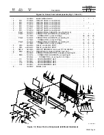
Страница 28: ...ABEL warning electric shock 1 7 602 177 SCREW set 250 20 x 250knrlpt sch stl 2 8 124 274 BRACKET mtg fan motor 1 9 R3 097 459 RESISTOR WW fxd 375W 20 ohm 1 10 FM 116 190 MOTOR 1 12HP 230V 1550RPM 50 60Hz 1 5A 1 010 467 CONNECTOR clamp cable 1 250 1 1 ST 800 707 A 2 3 4 5 6 9 10 7 8 Figure 7 5 Panel Rear w Components When ordering a component originally displaying a precautionary label the label sh...

Страница 29: ...t is present on primary ground ENVIRONMENTAL PROTECTION PACKAGE 043 049 Factory Internal machine components are sprayed with a protective polyurethane coating BALANCING PARALLELING CONTROL 042 810 Allows you to parallel two Deltawelds The control balances the power source s output amperage throughout its operating range This control plugs directly into the Deltaweld power supplies and is especiall...

Отзывы: