2
3
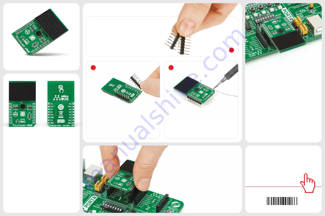
2. Soldering the headers
3. Plugging the board in
Once you have soldered the headers your
board is ready to be placed into the desired
mikroBUS
™
socket. Make sure to align the cut
in the lower-right part of the board with the
markings on the silkscreen at the mikroBUS
™
socket. If all the pins are aligned
correctly, push the board all the
way into the socket.
Turn the board upward again. Make sure
to align the headers so that they are
perpendicular to the board, then solder the
pins carefully.
Turn the board upside down so that
the bottom side is facing you upwards.
Place shorter pins of the header into the
appropriate soldering pads.
Before using your click board
™
, make sure
to solder 1x8 male headers to both left and
right side of the board. Two 1x8 male headers
are included with the board in the package.
4. Essential features
The MTCH6102 device supports taps,
doubletaps, swipes and scrolling gestures.
The small capacitive surface is optimized
for sungle-finger applications. The sensor
outputs 12-bit resolution coordinate
data (the I2C interface supports up to
400 kbps transfer rates). MTCH6102 also
incorporates power-saving features, such
as a configurable frame rate for sleep/idle
modes, as well as a separate standby and
active mode.
1
Touchpad click is a capacitive touch
input device driven by Microchip’s low-
powered
MTCH6102 controller
. The
touchpad surface is covered with a sheet
of black plastic to demonstrate the chip’s
support for cover layers (up to 3mm for
plastic, 5mm for glass) Touchpad click
communicates with the target MCU through
the mikroBUS™ I2C interface (SCL and SDA
pins), with additional functionality provided
by the Interrupt and RSTL pins. Designed to
use a 3.3V power supply.
1. Introduction
Touchpad click Manual v100
0100000091166
click
BOARDS
™
www.mikroe.com
Touchpad
click
Touchpad click Manual v100


