


[4]
-
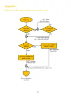
If the RUN pin is at a LOW logic level after the reset, the Click board™ will run as a DMX SLAVE. The MODE
LED indicator will be turned OFF. The response message is: "SLAVE RDY" (terminated by the <cr><lf> sequence)
-
If the RUN pin is at a HIGH logic level after the reset, the Click board™ will run as a DMX MASTER. The MODE
LED indicator will be turned ON. The response message is: "MASTER RDY" (terminated by the <cr><lf>
sequence)
Note: After the reset cycle, the Click board™ will first check the state of the ABR pin and then the state of the RUN pin.
The best practice is to first set the ABR and RUN pins to required states and then perform reset. By monitoring the INT
pin, it is possible to determine the status of the device during boot.
(MASTER) RUN mode
A rising edge on the RUN pin will cause the Click board™ to enter the RUN mode. The RUN pin is pulled up by an internal
resistor.
While operating in MASTER/RUN mode, the Click board™ relays data from the RX pin to the DMX bus, by generating
DMX frames. The UART input buffer length is of a (configurable) fixed size.
NOTE: No <cr> or <lf> control characters should be used to terminate the input. The parser will treat them as regular
values, causing a misalignment of the input buffer. Any buffer misalignment can be resolved with a short LOW pulse on
the RUN pin (while in RUN sub-mode).
The logic state of the RUN LED indicator will be inverted after each DMX frame, causing the LED to blink during normal
operation.
Once enough bytes have been received to fill the input buffer, it will be swapped with the output buffer and an interrupt will
signal that the input buffer is ready to receive a new data stream. However, the input buffer will not be swapped with the
output buffer until it is completely filled, so the output buffer will continuously cycle the most recently received data. This
may sound wrong for a typical data transfer situation, but in stage lighting situations, this is actually the perfect solution
that helps to avoid unwanted blackouts when there is no data at the input.
NOTE: The interrupt signal is synchronized with the DMX Frame Break event. Even if the input buffer is full, the
interrupt won't be triggered before the next Frame Break event. This helps to avoid filling the input buffer multiple times
in cases where it can be filled much faster than the output frame can be transmitted (e.g., a small input buffer at 115200
bps will be completely filled long before the entire DMX universe can be transmitted to the DMX bus at 250000 bps)
(SLAVE) RUN mode
A rising edge on the RUN pin will cause the Click board™ to enter RUN mode. The RUN pin is pulled up by an internal
resistor.
While operating in SLAVE/RUN mode, the Click board™ continuously receives DMX frames and decodes them into a
UART data string. The data string is available at the TX pin of the Click board™. Each DMX Frame Break event that marks
the beginning of a new DMX frame is signalized by an interrupt, which can be used for synchronization with the host
application.
The logic state of the RUN LED indicator will be inverted after each successfully received DMX frame, causing the LED
to blink during normal operation.


