


[3]
UART interface
The Click board™ uses the standard UART interface to exchange data with the host controller. Default UART parameters
are 115200, (8) data bits, (N)o parity, (1) stop bit. However, the Click board™ features an automatic baud rate configuration
and can use a wide range of different baud rates. More about selecting a custom baud rate can be found in the respective
chapter.
Other considerations
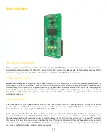
The digital signal might deteriorate with a large number of SLAVE devices connected. However, DMX Click offers a lot
of freedom and flexibility. The support for multiple DMX universes can be implemented within the lighting control
application itself, while the actual number of connected SLAVE devices can be increased by using two or more DMX Clicks
and using them to build so-called DMX Splitters and DMX Repeaters. These devices can also be purchased separately, in
specialized stage lighting stores.
A DMX network employs a daisy-chain connection topology. The last SLAVE device in the signal chain should always
have its termination resistor enabled in order to allow a proper impedance matching. DMX Click offers a small dip-switch
labeled as "TERMINATION" which enables the 120Ω termination resistor, when set to position "1".
Configuring the Click board™
How to reset the Click board™
It is always a good idea to reset the Click board™ before it is used. To perform reset, the RST pin of the mikroBUS™
should be pulsed LOW. After the Click board™ boots up, it is possible to select the new UART baud rate and operating
mode. The end of the boot sequence is signalized by a short pulse on the INT pin and a response message over the TX pin,
reporting the operating mode status (MASTER/SLAVE).
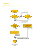
Automatic baud rate (ABR) configuration
If during the boot sequence the ABR pin is set to a HIGH logic level, the Click board™ will use the default UART settings,
as described above (115200, 8, N, 1). However, if during the boot sequence the ABR pin is set to a LOW logic level, the
STAT LED will start blinking while the INT pin will be held to a HIGH logic level. The Click board™ expects the value
of 0x55 (character "U") to be received over the UART interface (RX pin) at the desired baud rate. Once the character has
been received, the Click board™ will lock the detected baud rate and the INT pin returns to its idle state (LOW). The baud
rate remains locked until the next power or reset cycle.
Note: The Click board™ will attempt to detect the baud rate of any value sent via the RX pin. Sending values other than
0x55 will cause the baud rate to be detected incorrectly.
MASTER/SLAVE selection
After reset, the Click board™ will check the logic state of the RUN pin (PWM pin of the mikroBUS™). The logic state on
this pin determines whether the Click board™ boots up in MASTER or in SLAVE operating mode. Once set, the main
operating mode can't be changed until the next reset cycle. After the Click board™ completes the boot sequence, the RUN
pin becomes free to be used for RUN/CFG sub-mode selection. The end of the boot sequence is signalized by the INT pin
and a UART response message over the TX pin.


