

2
3
click
™
BOARD
www.mikroe.com
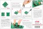
2. Soldering the headers
3. Plugging the board in
Once you have soldered the headers your
board is ready to be placed into the desired
mikroBUS
™
socket. Make sure to align the
cut in the lower-right part of the board with
the markings on the silkscreen at the
mikroBUS
™
socket. If all the
pins are aligned correctly,
push the board all the way
into the socket.
Turn the board upward again. Make sure
to align the headers so that they are
perpendicular to the board, then solder the
pins carefully.
Turn the board upside down so that
the bottom side is facing you upwards.
Place shorter pins of the header into the
appropriate soldering pads.
Before using your click
™
board, make sure
to solder 1x8 male headers to both left and
right side of the board. Two 1x8 male headers
are included with the board in the package.
4. Essential features
Proximity 2 click™ is an excellent
prototyping platform for the MAX44000
IC. The chip (in a optically transparent
package contains an
array of photodiodes
that convert light to current, which is in turn
converted into a digital value. With only a
2mm x 2mm footprint
, MAX44000 is ideal
for handheld accessories (smartphones
and similar). The wide range and low power
consumption makes the sensor suitable
for presence and ambient detection in
industrial sensors as well.
1
Proximity 2 click™ features
MAX44000
, an
IC that integrates a
proximity as well as an
ambient light sensor
. The light sensor has
a
dynamic range of 0.03 to 65.535 lux
. The
IR proximity detector is matched with an
integrated IR LED driver (for the
onboard
high power infrared LED
). The detecting
range is Proximity 2 click™ communicates
with the target board microcontroller
through mikroBUS™ I2C (SCL, SDA), and
INT lines. It’s designed to use a 3.3V power
supply only.
Proximity 2
click
™
1. Introduction


