12
Instruction in synergy programming of the MWF
10/11/21
The KMX 550 and FLEX range with MWF10/11/21 can
be equipped with a synergy kit, which enables
synergetic adjustment of the welding machine.
Contrary to traditional MIG/MAG welding where ad-
justment of both welding current as well as welding
voltage is necessary, synergetic adjustment is
characterised by adjustment with only one knob.
Welding current can be adjusted with the wire feed
speed knob and then welding voltage changes auto-
matically in relation to adjustment. This provides e.g.
the possibility of torch adjustment of the welding
current and a special crater filling function, which can
be used when the function selection knob (pos. 3)
(page 41) is set a 4-times welding.
Wires feed units with synergy kit have a programme
selection knob (pos. 18) and a crater filling adjustment
knob (pos. 17).
Crater filling
In order to avoid crater formation at the end of a
welding seam this function reduces the welding current
immediately before ending the welding. The function
can be used when selecting 4-times welding and
thereafter by pressing the torch trigger at the end of the
welding. During crater filling the size of the welding
current is adjusted on the crater filling adjustment knob
(pos. 17) as a percentage of the welding current during
normal welding. This function can only be effected
when using synergy adjustment of the welding
machine.
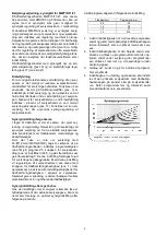
Synergy adjustment according to table
A table with synergy welding programmes can be seen
in the cover to the wire drive roll. This table is guidance
on how to choose programme number, trim value and
inductor tap according to planned welding process.
The welding process is defined as selection of
material, wire diameter and shielding gas.
The table shows that programme number P9 (pro-
gramme selector pos. 18), trim value 22.5 (welding
voltage knob pos. 2) and inductor tap 3 matches
welding with Fe//Ø1.2mm//ArCO2 (80/20). Adjustment
is necessary before welding. Adjustment of the welding
current is only possible with the wire feed speed knob
(pos. 1) in this particular machine setting. Please be
aware of the fact that all adjustment facilities in wire
feed speed may not be weldable in practice. This table
gives a guidance on which wire feed speed to be used
for welding of different material dimensions.
The welder is able to make his own synergy welding
programme. It is then necessary to use the following
process:
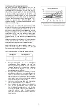
Adjust the programme selector to the following setting:
Wire diameter
Programme number
0.8
P2
1.0
P5
1.2
P7
1.6
P10
1.
Adjust the wire feed speed to the lowest value and
adjust the optimum trim value with the voltage
adjustment knob. The trim value is readable when
the torch trigger is not activated.
2.
Adjust the wire feed speed to the highest value in
question and adjust the programme number to the
optimum value during welding (when the number
on the programme selector is increased the
voltage increases simultaneously during welding).
3.
Repeat eventual point 3 and 4 in order to ensure
that it is the optimal programme.
4.
The programme is finished, and the machine can
now be adjusted to the planned welding current
with the wire feed speed knob on the control panel
or the welding torch. Please note programme
number, trim value and process data for later use.
Содержание MWF 10
Страница 4: ...4...
Страница 41: ...41 MIG MAG WIRE FEED UNIT...
Страница 42: ...42...
Страница 44: ...44 MWF 8 10 11 21...
Страница 46: ...46 MWF 11 LATERALLY REVERSED...
Страница 47: ...47 MWF 15 LATERALLY REVERSED...
Страница 48: ...48...
Страница 60: ...60 TR DFREMF RING WIRE FEED UNIT DRAHTVORSCHUBEINHEIT DISPOSITIF DE GUIDAGE DE FIL 14 15...
Страница 64: ...64...
Страница 65: ......


