


10
Introduction
Models MWF are wire feed units designed for
connection to a MIG/MAG welding power source. All of
the wire feed units are fitted with 4-roll wire drive units
to the wire feed motor by a gearwheel. This ensures
stable feeding of the wire. Models MWF 8/10/11 are
closed wire feed units with internal reels of wire, and
MWF 21 and 25 have an external reels of wire.
Connection to power source
Models MWF 8, 10, 11 and 21 are wire feed units
designed for connection to MIGATRONIC power
sources MIG 385, 445, 545 and KMX 550 plus other
power sources with the same specifications for controll
cable to the wire feed unit (see diagram page 44).
Models MWF 15 and 25 are wire feed units designed
for connection to MIGATRONIC power sources BDH
Pulse Sync
400 and 500 (see diagram page 45). To
obtain the best exactness of the wire speed the motor
is tacho-controlled.
Configuration
MIGATRONIC disclaims all responsibility for damaged
cables and other damages related to welding with
under sized welding torch and welding cables
measured by welding specifications e.g. in relation to
permissible load.
Important!
In order to avoid destruction of plugs
and cables, good electric contact is
required when connecting earth
cables and intermediary cables to
the machine.
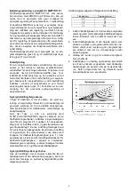
Adjustment of wire brake
The wire brake must ensure that the wire reel brakes
sufficiently quickly when welding stops. The required
brake force is depending on the weight of the wire reel
and the maximum wire feed speed. A brake torque of
1.5-2.0 Nm will be satisfactory for most applications.
Adjustment:
-
Dismount the control knob by placing a thin screw
driver behind the knob and thereafter pull it out
-
Adjust the wire brake by fastening or loosening the
self-locking nut on the axle of the wire hub
- Remount the knob by pressing it back into the
groove.
Dispose of the product according to local
standards and regulations.
www.migatronic.com/goto/weee
Technical data
MWF 8
MWF 10
MWF 11
MWF 15
MWF 21
MWF 25
100% duty cycle
425
325
425
425
425
425
A
60% duty cycle
550
400
550
550
550
550
A
Wire speed
1.3-18
1.7-24
1.7-24
1.7-24
1.7-24
1.7-24
m/min
Mains voltage
40
40
40
40
40
40
V AC
Efficiency
250
250
250
250
250
250
VA
Torch connection
EURO
EURO
EURO
EURO
EURO
EURO
Dimension wire reel
300
300
300
300
300
300
mm
Separate wire reel
no
no
no
no
yes
yes
Separate intermediary cable
no
no
yes
yes
yes
yes
Protection class *
IP23
IP23
IP23
IP23
IP23**)
IP23**)
Weight (without accessories)
28
28
28
28
16
16
kg
+ weight sliding bracket
-
-
-
-
6
6
kg
+ weight wire cassette
-
-
-
-
1.5
1.5
kg
+ weight bracket
-
-
-
-
2
2
kg
Dim. (lxbxh) standard
68x22x49
68x22x49
68x22x49
68x22x49
37x27.5x23.5
37x27.5x23.5
cm
Dim. (lxbxh) w/bracket
-
-
-
-
71x27.5x37
71x27.5x37
cm
Dim. (lxbxh) m/trolley
-
-
-
-
71x27.5x41
71x27.5x41
cm
* Equipment marked
IP23
is designed for indoor and outdoor applications.
**The protection class does not include the wire reel.
Содержание MWF 10
Страница 4: ...4...
Страница 41: ...41 MIG MAG WIRE FEED UNIT...
Страница 42: ...42...
Страница 44: ...44 MWF 8 10 11 21...
Страница 46: ...46 MWF 11 LATERALLY REVERSED...
Страница 47: ...47 MWF 15 LATERALLY REVERSED...
Страница 48: ...48...
Страница 60: ...60 TR DFREMF RING WIRE FEED UNIT DRAHTVORSCHUBEINHEIT DISPOSITIF DE GUIDAGE DE FIL 14 15...
Страница 64: ...64...
Страница 65: ......