background image

M.-Nr. 05 719 360 / 03

7

6

Содержание C 4060

Страница 1: ...5 PT 5135C PT 5136 PT 7135C PT 7136 80 mm 35 mm WS 5073 T 6185 90 mm 28 mm WS 5425 WS 5426 WS 5435 WS 5436 WS 5445 WS 5446 T 5205 T 5206 42 mm 28 mm Kassiergerät C 4060 C 4065 C 4070 montieren und anschließen C 4060 C 4065 C 4070 coin mechanism fitting and connection Montage et branchement du monnayeur C 4060 C 4065 C 4070 Muntautomaat C 4060 C 4065 C 4070 plaatsen en aansluiten Montering og tilko...

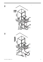
Страница 2: ...Löchern fixieren und Kassiergerät mit beigefügtem Befesti gungsmaterial auf dem Maschinendeckel befestigen c Angestanztes Durchführungsloch in der Rückwand herausbrechen Kabelzugentlastung 2 M Nr 01 636 051 aus Zubehör nehmen Anschlusskabel 3 durchführen Bild 3 Ste cker 4 auf vorhandene 7 pol Rundkupplung 5 im Gerät aufstecken Achtung bei C 4065 C 4070 evtl Adapter 8 erforderlich siehe Hinweiszett...

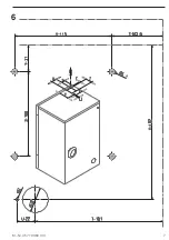
Страница 3: ...us Sicherheitsgründen darf das Anschlusskabel 2 50 m Länge nicht überschreiten III PT 7251 PT 7331 a Die Bohrschablone Bild 7 auf Maschinendeckel fixieren und Löcher C 6 5 mm bohren b Am Kassiergerät die Frontblende öffnen die Gummimatte auf dem Maschinendeckel über den gebohrten Löchern fixieren und Kassiergerät mit beigefügtem Befestigungsmaterial auf dem Maschinendeckel befestigen c Kabelzugent...

Страница 4: ...4 M Nr 05 719 360 03 1 ...

Страница 5: ...M Nr 05 719 360 03 5 2 3 ...

Страница 6: ...6 M Nr 05 719 360 03 4 5 ...

Страница 7: ...M Nr 05 719 360 03 7 6 ...

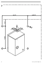
Страница 8: ...8 M Nr 05 719 360 03 7 ...

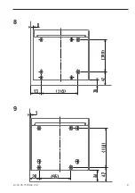
Страница 9: ...M Nr 05 719 360 03 9 9 8 ...

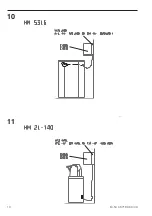
Страница 10: ...10 M Nr 05 719 360 03 11 10 ...

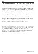
Страница 11: ...g 2 1 on the machine lid above the drilled holes and secure the coin mechanism in position on the machine lid with the fixings supplied If necessary fit the reinforcement Mat no 04 043 580 and locking plate Mat no 04 438 220 7 c Remove the cable strain relief Fig 2 2 from the rear panel pass the connection cable 3 through and connect the plug 4 to the 7 pole round connector 5 already fitted in the...

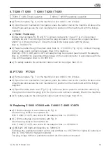
Страница 12: ...pter Mat no 05 688 610 With C 4060 and C 4070 proceed in accordance with the wiring diagram supplied with the machine e Open the cable strain relief Fig 3 2 in the rear panel pass the connection cable 3 through and connect the plug 4 to the round connector The coin mechanism fitting kit BSK 01 Article no 59 4000 13 Mat no 04 808 770 is required f For safety reasons the connection cable 3 must not ...

Страница 13: ...0 e For safety reasons the connection cable must not be longer than 2 5 m III PT 7251 PT 7331 a Fix the template Fig 7 on the machine lid and drill 6 5 mm C holes b Open the coin mechanism front panel place the rubber mat on the machine lid above the drilled holes and secure the coin mechanism in position on the machine lid with the fixings supplied c Open the cable strain relief Fig 5 11 in the r...

Страница 14: ...e couvercle de la machine au dessus des orifices percés et fixer le monnayeur avec le matériel de fixation fourni sur le couvercle de la machine monter un renfort MTS M Nr 04 043 580 et une équerre de fixation MTS M Nr 04 438 220 7 le cas échéant c Enlever le passe câble 2 croquis 2 de la paroi arrière faire passer le câble de connexion 3 et brancher le connecteur 4 sur la prise ronde à 7 pôles 5 ...

Страница 15: ... suivant la notice Adapter M Nr 05 688 610 Pour C 4060 se conformer au schéma électrique joint à la machine e Ouvrir le passe câble 2 croquis 3 dans la paroi arrière faire passer le cordon d alimentation 3 et brancher le connecteur 4 sur la prise ronde BD 01 Art Nr 59 4000 13 M Nr 04 808 770 est nécessaire Pour des raisons de sécurité le cordon d alimentation 3 ne doit pas dépasser 2 50 m Ic WS 50...

Страница 16: ... des raisons de sécurité le cordon d alimentation 3 ne doit pas dépasser 2 50 m III PT 7251 PT 7331 a Fixer le gabarit de perçage croquis 7 sur le couvercle de la machine et percer des orifices C 6 5 mm b Ouvrir la façade du monnayeur ajuster l isolant en caoutchouc sur le couvercle de la machine au dessus des orifices percés et fixer le monnayeur avec le matériel de fixation fourni sur le couverc...

Страница 17: ...nedeksel boven de boorgaten en bevestig de muntautomaat met het bijgeleverde bevestigingsmateriaal op het machinedeksel eventueel MTS versteviging M Nr 04 043 580 en MTS diefstalbeveiliging M Nr 04 438 220 7 monteren c Haal de kabeltrekontlasting 2 afbeelding 2 uit de achterwand Voer de verbindingskabel 3 door Steek de stekker 4 op de aanwezige 7 polige ronde koppeling 5 in het apparaat Let op Voo...

Страница 18: ...4070 volgens instructieblad Adapter M Nr 05 688 610 Bij C 4060 overeenkomstig het schakelschema dat bij de machine is gevoegd e Open de kabeltrekontlasting 2 afbeelding 3 in de achterwand Voer de verbindingskabel 3 door Steek de stekker 4 op de ronde koppeling BSK 01 Art Nr 59 4000 13 M Nr 04 808 770 vereist f Om veiligheidsredenen mag de aansluitkabel 3 niet langer zijn dan 2 50 m Ic WS 5073 T 61...

Страница 19: ...ansluitkabel niet langer zijn dan 2 50 m III PT 7251 PT 7331 a Leg de boorsjabloon afbeelding 7 op het machinedeksel en boor gaten C 6 5 mm b Open het frontpaneel van de muntautomaat Fixeer de rubberen mat op het machinedeksel boven de boorgaten en bevestig de muntautomaat met het bijgeleverde bevestigingsmateriaal op het machinedeksel c Open de kabeltrekontlasting 11 afbeelding 5 in de achterwand...

Страница 20: ... over de borete hullene og fest myntautomaten på maskindekselet med vedlagte festemateriell monter evt MTS forsterkning M Nr 04 043 580 og MTS sikringsplate M Nr 04 438 220 7 c Ta kabelstrekkavlastningen 2 fig 2 ut av bakveggen før tilkoblingskabel 3 i gjennom og sett pluggen 4 på den eksisterende 7 pols rundkoblingen 5 i maskinen NB For C 4065 C 4070 er evt adapter 8 nødvendig se henvisningssedde...

Страница 21: ...enhold til henvisningsseddel adapter M Nr 05 688 610 For C 4060 iht koblingsskjemaet som følger med maskinen e Åpne kabelstrekkavlastningen 2 fig 3 i bakveggen før tilkoblingskabelen 3 i gjennom og sett pluggen 4 på rundkoblingen BSK 01 Art Nr 59 4000 13 M Nr 04 808 770 er nødvendig f Av sikkerhetsgrunner må lengden på tilkoblingskabelen 3 ikke overskride 2 50 m Ic WS 5073 T 6185 b Åpne fronten på...

Страница 22: ...etsgrunner må lengden på tilkoblingskabelen ikke overskride 2 50 m III PT 7251 PT 7331 a Fest boresjablonen fig 7 på maskindekselet og bore hull C 6 5 mm b Åpne fronten på myntautomaten fest gummimatten på maskindekselet over de borete hullene og fest myntautomaten på maskindekselet med vedlagte festemateriell c Åpne kabelstrekkavlastningen 11 fig 5 i bakveggen før tilkoblingskabelen 12 gjennom og...

Страница 23: ...hastinlaite kiinnitetään koneen kanteen mukanatoimitettavalla kiinnitysmateriaalilla mahdollisesti tulee lisäksi asentaa muutossarja vahvistinlevy osa n o 04 043 580 ja muutossarja varmistinlevy osa n o 04 438 220 7 c Kaapelin vedonpoistaja 2 kuva 2 irroitetaan takaseinästä liitäntäjohto 3 työnnetään läpi ja pistoke 4 kiinnitetään laitteen 7 napaiseen kierrekytkimeen 5 Huom C 4065 C 4070 ssa tarvi...

Страница 24: ...sti C 4060 ssa toimenpide suoritetaan koneessa olevan kytkentäkaavion mukaisesti e Kaapelin vedonpoistaja 2 kuva 3 takaseinässä avataan liitäntäjohto 3 johdetaan läpi ja pistoke 4 kiinnitetään kierrekytkimeen Lisäksi vaaditaan rahastinlaitteen asennussarja 01 artik n o 59 4000 13 osa n o 04 808 770 f Turvallisuussyistä ei liitäntäkaapeli 3 saa ylittää 2 50 metrin pituutta Ic WS 5073 T 6185 b Rahas...

Страница 25: ...mukaisesti e Turvallisuussyistä ei liitäntäkaapeli saa ylittää 2 50 metrin pituutta III PT 7251 PT 7331 a Porauskaavain kiinnitetään koneen kanteen ja porataan C 6 5 mm kokoiset reiät b Rahastinlaitteessa oleva etupaneli avataan kumimatto asetetaan koneen kannen päällä olevien reikien päälle ja rahastinlaite kiinnitetään koneen kanteen mukanatoimitettavalla kiinnitysmateriaalilla c Kaapelin vedonp...

Страница 26: ... 2 ao tampo da máquina através dos orifícios e fixar o mealheiro ao tampo utilizando o material fornecido junto montar eventualmente o reforço MTS Mat nr 04 043 580 e chapa de segurança 7 mat nr 04 438 220 c Retirar a chapa de passagem de cabos 2 fig 2 da parede traseira passar o cabo 3 e ligar a ficha 4 ao acoplamento redondo de 7 pólos 5 existente na máquina Atenção no caso de C 4065 C 4070 even...

Страница 27: ...at nr 05 688 610 No caso do C 4060 de acordo com o esquema de ligação fornecido com a máquina e Abrir o passador do cabo 2 fig 3 situado na parede posterior passar o cabo 3 e ligar a ficha 4 ao acoplamento redondo É necessário um conjunto BSK 01 Art Nr 59 4000 13 mat nr 04 808 770 f Por motivos de segurança o cabo de ligação eléctrico 3 não deve ultrapassar os 2 50 m de comprimento Ic WS 5073 T 61...

Страница 28: ...ança o cabo de ligação eléctrico não deve ultrapassar os 2 50 m de comprimento III PT 7251 PT 7331 a Fixar o molde fig 7 ao tampo da máquina e perfurar com 6 5 mm de C b Abrir a parte frontal do mealheiro fixar a placa de borracha ao tampo da máquina através dos orifícios efectuados e fixar o mealheiro ao tampo utilizando o material fornecido junto c Abrir o passador de cabos 11 fig 5 no painel po...

Страница 29: ...sul coperchio macchina all altezza dei fori preparati e la gettoniera sempre sul coperchio macchina con l allegato materiale di fissaggio ev montare rinforzo MTS n d ord 04 043 580 e lamiera di fissaggio MTS n d ord 04 438 220 7 c Togliere il passacavo 2 figura 2 dalla parete posteriore far passare il cavo di alimentazione 3 e innestare lo spinotto 4 sull accoppiamento circolare a 7 poli 5 nella m...

Страница 30: ...atore n d ord 05 688 610 Per la C 4060 attenersi allo schema elettrico allegato alla macchina e Aprire il fermacavo 2 figura 3 nella parete posteriore far passare il cavo di alimentazione 3 e innestare lo spinotto 4 sull accoppiamento circolare Necessario BSK 01 n d ord 59 4000 13 n d ord 04 808 770 f Per motivi di sicurezza il cavo di alimentazione 3 non deve superare i 2 50 m di lunghezza Ic WS ...

Страница 31: ...otivi di sicurezza il cavo di alimentazione non deve superare i 2 50 m di lunghezza III PT 7251 PT 7331 a Fissare la sagoma di foratura figura 7 sul coperchio macchina e praticare i fori di diametro C 6 5 mm b Aprire il pannello frontale sulla gettoniera fissare il tappetino di gomma sul coperchio macchina attraverso i fori preparati e la gettoniera sempre sul coperchio macchina con l allegato mat...

Страница 32: ... máquina sobre los orificios taladrados y asegure el aparato recaudador a la tapa de la máquina con el material de fijación adjunto si fuera necesario monte el refuerzo MTS nº de mat 04 043 580 y la chapa de seguridad MTS nº de mat 04 438 220 7 c Retire el prensacables 2 fig 2 de la pared posterior introduzca el cable de conexión 3 y conecte la clavija 4 al acoplamiento esférico de 7 polos 5 del a...

Страница 33: ...a nota Adaptador nº de mat 05 688 610 En el modelo C 4060 siga el esquema de conexiones que se adjunta a la máquina e Abra el prensacables 2 fig 3 de la pared posterior introduzca el cable de conexión 3 y conecte la clavija 4 al acoplamiento esférico BSK 01 nº de art 59 4000 13 nº de mat 04 808 770 necesario f Por motivos de seguridad el cable de conexión 3 no debe sobrepasar los 2 50 m de longitu...

Страница 34: ...de conexión no deberá sobrepasar los 2 50 m de longitud III PT 7251 PT 7331 a Fije la plantilla de taladros fig 7 a la tapa de la máquina y taladre orificios C 6 5 mm b Abra el panel frontal del aparato recaudador fije la estera de goma a la tapa de la máquina sobre los orificios taladrados y asegure el aparato recaudador a la tapa de la máquina con el material de fijación adjunto c Abra el prensa...

Страница 35: ...ο λαστιχένιο κάλυµµα 1 Εικ 2 στο καπάκι της συσκευής πάνω απ τις τρύπες που ανοίξατε και στερεώστε τον κερµατοδέκτη µε τα υλικά στερέωσης στο καπάκι της συσκευής ενδεχοµένως τοποθετείστε το MTS M Nr 04 043 580 και το MTS λαµαρίνα στερέωσης M Nr 04 438 220 7 c Αφαιρέστε το στήριγµα του καλωδίου 2 Εικ 2 απ το πίσω τοίχωµα περάστε µέσα το καλώδιο σύνδεσης 3 και βάλτε το φις 4 στον υπάρχοντα 7πολικ συ...

Страница 36: ...ξης αντάπτορα M Nr 05 688 610 Στο C 4060 βάσει του σχεδίου που υπάρχει στη συσκευή e Ανοίξτε το στήριγµα του καλωδίου 2 Εικ 3 στο πίσω τοίχωµα περάστε µέσα το καλώδιο σύνδεσης 3 και βάλτε το φις 4 στο συµπλέκτη Είναι απαραίτητο το BSK 01 Art Nr 59 4000 13 M Nr 04 808 770 f Για λ γους ασφαλείας το καλώδιο σύνδεσης 3 δεν πρέπει να ξεπερνά τα 2 50 m µήκος Ic WS 5073 T 6185 b Ανοίξτε τη µετώπη του κερ...

Страница 37: ... e Για λ γους ασφαλείας το καλώδιο σύνδεσης δεν πρέπει να ξεπερνά τα 2 50 m µήκος III PT 7251 PT 7331 a Στερεώστε το πατρ ν Εικ 7 στο καπάκι και ανοίξτε τρύπες C 6 5 b Ανοίξτε τη µετώπη του κερµατοδέκτη τοποθετήστε το λαστιχένιο κάλυµµα στο καπάκι της συσκευής πάνω απ τις τρύπες που ανοίξατε και στερεώστε τον κερµατοδέκτη µε τα υλικά στερέωσης στο καπάκι της συσκευής c Αφαιρέστε το στήριγµα του κα...

Отзывы: