Midway Mortal Kombat Скачать руководство пользователя страница 1

Содержание Mortal Kombat

Страница 1: ......

Страница 2: ...buttons to attack an opponent Use the joystick to make the screen player jump or duck and move left or right Use joystick and button combinations to discover secret moves MIDWAY Manufacturing Company...

Страница 3: ...I MORTAL KOMBAT...

Страница 4: ...2 CPU Sound Tests 1 13 Monitor Patterns Burn in Test 1 14 Coin Bookkeeping 1 1 5 Game Audits 1 16 Game Adjustments 1 17 Standard Pricing Table 1 19 Custom Pricing Table 1 20 Uttlilles 1 21 Troubleshoo...

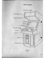
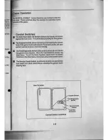
Страница 5: ...MORTAL KOMBAT Operation 1 1 SECTION one...

Страница 6: ...electrical shock use the replacement fuse which is specified in the parts list for this game The replacement fuse must match the original fuse in fuse type voltage rating and current rating MONITOR PR...

Страница 7: ...abinet Wiring Diagram seelion 3 and check to see that all cable conneelors are correctly secured DO NOT FORCE CONNECTORS Watch lor damaged connectors and avoid making reversed connections 7 Determinet...

Страница 8: ...luorescenl Lamp Assembly Screened Marquee LL Speaker Cap Assembly I I I 25 Monilorr_llJ j Bezel _ i InslruclionCard COnirOI Panel Assembly 2 Bullons Coin Door 4 Fronl Door AssembIY iH j LJl Front View...

Страница 9: ...Cabinet Assembly Venl Cover Chassis Panel Assembly CPU Board __HJ Sound Board ttt H U _ Swilcher Power SUPP Y 1tn tt 21 On Olf Swilch e Power Pack ASSembIY_r JJ Line Cord I Rear View 1 5...

Страница 10: ...ires Reclamp th latches Note To remove the control panel for bench servicing reach Ih 9 the coin door opening and release the latches localed h sides of the control panel Be carelui not to reach strai...

Страница 11: ...power to the game Remove the marquee glass The speakers pull out from the front of the cabinet Be sure 10 disconnect the cabling and remove the nuts on the mounting screws belore attempting to pull th...

Страница 12: ...TING The game Ihen begins Allracl Mode Insert Ihe desired amounl of coins or lokens Press Ihe approp Slart bullon Player Controls o Start Buttons Each player has a Start Bullon which allows himlher to...

Страница 13: ...level 01 the game music and speech For greater profits set your game s volume level at a nice loud setting TheTesUDlagnostic Switch slide switch allows you to activale the game s Menu System Move the...

Страница 14: ...ch Bank 2 to activate the Main Menu shown betow Game adjustments bookkeeping and diagnostics are all acces sible rom this menu Move any joystick up or down 10 cycle through the menu options Notice tha...

Страница 15: ...Menu Dfagnostlc Menu Switch Test The Switch Test allows the operator to test the switches on the control panel and the coin door Seleclthe Swilch Test by using any joyslick to highlight the Switch Te...

Страница 16: ...new selling Press any control panel bullon to return to the Diagnostic M DIP Switch 1 Settings Table SWI SW2 SW3 SW4 sws SW6 SW7 SW8 VlolenclOn Off On Blood n gam Off On Low Blow In glm Off On Attract...

Страница 17: ...o continue the test JUlina Board Test Sound Test allows listening to some of the sounds that this Is capable of producing This test also emits a tone for each that Is detected the Sound Board Test wit...

Страница 18: ...th red green and blue level adjuslmenls Each color should appear sharp and clear The CROSSHATCH PADERNS lesllills Ihe screen wilh a grid and a series 01 dOls The grid and Ihe dols should be clear The...

Страница 19: ...oins credils or plays lor each item To exil Coin Bookkeeping move any joystick 10 selecl RETURN TO MAIN MENU Ihen press any conlrol panel bullon 10 aclivale II Lell Slot Coins RIght SIOI Coins Third S...

Страница 20: ...of Ihe lable names Ihe Audil item Ihe righl side shows Ihe amounl of play Hours Game Was Played TOlal Play Time Hours Played Wllh 1 Player Hours Played Wllh 2 Players Tolal Plays Conllnues Taken Bum l...

Страница 21: ...l1ing value Ihen press any control panel bul10n to lock in the new value and relurn to the Adjustment Menu Move Ihe joysllck up to Increase the sel1ing value move the joyslick down decrease the sel1in...

Страница 22: ...redils required to continue a game This option is being adjusted from the Dip Swilch Sellings See page 1 20 Modify the setting value with any joystick Press any control panel button to lock in a new v...

Страница 23: ...German 4 1 1 OM 51 5 OM 10M 50M German EGA 1 1 OM 212 OM 615 OM 50M 10M 20M France 1 215 F 5110 F 10 F France 2 215 F 4 10 F 10 F France 3 115 F 3 10 F SF 10 F France 4 115 F 2 10 F SF 10 F France EC...

Страница 24: ...n in the lourth chute see units credit 2 This is the number 01 coin units required to buy one credit 3 One bonus credit is awarded allerthis many coin units have accumulated 4 No credils will be award...

Страница 25: ...Factory Restore Return To Main Menu Utilities Menu Move any JOYSlick 10 selecl an ilem Irom the Utilities Menu Ihen press any conlrol panel obutton to activale Ihal ilem Alter an ilem has been actival...

Страница 26: ...MMA Connector Check interboard wiring from CPU Board to thE Sound Board Check thE 1A S B luse Check lor open wires between the joystick and CPU Board Check lorconlamination on joystick swilch contacts...

Страница 27: ...MORTAL KOMBAT Parts 2 1 SECTION two...

Страница 28: ...nch Toggle Lalch Long Arm Key T 20 555 Bulb 6 3V Marquee Marquee Relainer Speakers Speaker Cap Assembly Piezo Speaker Cable Speaker Cable Speaker Grille Cap 10 non pol 50V 20 Tweeler Speaker 40 15W 6...

Страница 29: ...5017 09044 00 5102 10310 00 5610 13326 00 5731 06569 00 5731 10356 00 5733 12869 00 Fluorescent Lamp Assembly Fluorescent Housing Bracket Housing Mounling Brkt lighl Fixture 18 Fluorescent Bulb 15 W...

Страница 30: ...nsion Cable Sound Power Speaker Cable Video Signal Cable Swilch Power Cable Control Panel Cable Main Harness Speaker Cable line Filler Jumper G I Jumper Cable 20 pin Ribbon Cable 2 4 H 13265 H 13378 H...

Страница 31: ...A 15202 1 Power Supply Switcher Assembly Part Number H 15203 01 10500 01 10573 20 9700 J s 0 il 1 a 0 il 2 5 Description Swilch Power Cable Mounting Bracket Shield PIS Switcher Supply J I J s Z N 1 i...

Страница 32: ...o 1l1i O I 11111 3 tillf L U I94 QOJOI Q o A 13234 40025 CPU Board Assembly o 2 6 o o...

Страница 33: ...5311 12285 00 U51 U73 U82 IC 74HC573 A 5346 40025 7 lJtl5 C PLO Miscol aneous Control 534f 12014 00 U66 U69 IC 4 64 DRAM 64 J 4 A 5343 40025 1 U8 C Game EPR foA 5283 10552 00 U83 1C 74FG4 A 5343 40025...

Страница 34: ...A 14732 40025 Sou nd Board Assembly 2 8...

Страница 35: ...erator 501G 09C 36 OO R4 R30 R90 1000 Res 5 1 4W A S346 4002S 9 U 8 c PW Sound 5010 09187 00 R27 lSOO Res 5 1 4W 5371 T 1087 00 U28 10 YM3012 CAC 501 09I5 OO A83 2200 Res 5 10 1 4 1 5433 12S162 00 U c...

Страница 36: ......

Страница 37: ...MORTAL KOMBAT SECTION three Schematics and Wiring Diagrams...

Страница 38: ...nterboard Wiring Diagram e 5 J I l PI PO J A bbot CMIo Pow From N J loCPUJ8 CPUJ2 P5 w I w Sound Board l N B N P1 JI J2 J3 Pow ScM ld Pow To COntfd Panel M PO CoInMo Y Unlt CPU Board N A JOB FromPl J7...

Страница 39: ...E l CI IV 0 CI c Gi c I Jl J If 1 I IIII I I I I I I I I I I I I I I I _ __ _N G ___ J 1 H r I I I l i I I il I I I I I I I I I I I I I I I I I I CPU BOARD 3 3 I fil o...

Страница 40: ...RED FOR 115 VOLT OPERATION 1 TI R HES AGE CTION J E VoI1aoe Seledbl Tablt Transformer Chart 15 PIN CONNECTOR 3 PIN CONNECTOR TO MONrrOR r t 5 ffi 120Y ISOlATED FOR MONITOR AND POWER SUPPt Y 2 1 15 1 1...

Страница 41: ...I J IT 9 i I d I T l J r eJ i J Q l i h P I CD l 0 lei Il 0 1 c t 3 5 _ SO 1 i I I...

Страница 42: ...I J 1 I r l 3 6...

Страница 43: ...lQ Q om 3 7...

Страница 44: ...i D 0 r JCD Q UII 3 8...

Страница 45: ...101 a 000 i I t J W J 11 1 tu J IT 1 i i jlTli j i i i1U 1 IJJ 11 3 9 E li li U l t L o I UJJ I I J I I I I lJ_ I I 1i T I I I m...

Страница 46: ...CD CD Ql D UW I u l WUIJ 3 I rwIIlIT IT 9 ifff 3 10 10000 u U...

Страница 47: ...1 I _ r I 0 0 0 Q o Q om i 0 I I i i I L 0 L _ J I j 1 j I a c __ J i l r r r J 1 I I 3 11 i I I O l j...

Страница 48: ...i J t t CD o co n 1 1m o 38o o 11I111 r mlill _ IIIIIII 3 12 103S80...

Страница 49: ...1 JIJ a gsoS S I 01 K i IoL 0 1 I o 1 JJ IJ I j I t I r jj1j 0 38 3801 1 80 a tWJ e 1 1 4 1 T4 1J J r r L JILl 01003 01 3S8 I I t t1 I 0 1 Jl L I l I m m t JIJ j11 J o SS 080 1 3 n 80 1 0 S I e i U j...

Страница 50: ...111 i m im mm g g i I m 11 11 I JJ11 HiHm mm j I 11 c I 1 iHfH ig r eE j l 1 9 I J J L L JJ11 i M im ii m i j r i i9 T ij CO l l i 1 i f 6iW t 0 0 3 14...

Страница 51: ...CD i 0 Ja Il 0 1 i j j j J j j I_ O 1 J 9 9 OJ l 3 15...

Страница 52: ...U 0 N CD 11 11 0 1 3 16...

Страница 53: ...P i I i I I s J I 5 i r O r r 0 I c II 1 1 Sr j i J S JjjjjJi i U T 0 M T Ql D UCI 3 17...

Страница 54: ...I j o 3 18...

Страница 55: ...o g CD o It 0 3 19 0 _ f fGrft n _tnnn...

Страница 56: ...IL I W i 0 GI Q O J 3 20 _ t a _ r llll _ o 0 1 _ 0 c 0 0 o 0 o u...

Страница 57: ...1 2 3 4 r 0 I t 1 1 tI tI II f SV c o C II Ull n UI1 ff I 1 _ IU U UI1 B 1 UI1 I 1 nnr A MI HOlE MIGHOl HI HOl e 1 1 2 1 1 1 t II It It 1 2 3 4...

Страница 58: ...5 n u 5 n 6 U19 6 II n 7 7 It 1 1 n 8 Sound Board Sheet 1 of 4 8 0 c B A 3 21...

Страница 59: ...5 5 u z 6 u 6 7 8 D c T B I A Sound Board Sheet 2 of 4 7 8 3 22...

Страница 60: ...1 2 D H rr c I 5 B t A 1 2 3 rr rr I 0 3 It rr 4 4 Ute...

Страница 61: ...7 ZZ I1 1 o c B A 1 H l I f 1 2 I I 2 I U tt 06 U 3 i H 3 4 fl V 4...

Страница 62: ...5 6 5 6 7 8 D 3 23...

Страница 63: ...fl t H W 1 1 4 f lI Ir HI I 1 lfi rl tt 1I _ f 111 T L u HI h 111 1 L _________ _ D RR L l H H I r Rh FFFI h_ L H I _ I FFFR tI Rh F_ n orr t l 1 F 1tl r l lH li r yt tl __ I jl l L l tt rl I H l tH...

Страница 64: ...5 1 1 1 11 0 1 11 ron r Tn T 1 __ __ lJ ___ tI I It 7f r u U II o if I H T I H 1 6 5 6 I It r 7 1 hlr 7 8 Sound Board Sheet 4 of 4 hOI 8 0 c B A 3 24...

Страница 65: ...k Orange Brown Orange Red Orange Orange Yellow Orange Green Orange Blue Oranga Violet Orange Gray Black Yellow Blue Yellow Black Yellow Brown Yellow Red Yellow Orange Yellow Violet Yellow Gray Violet...

Страница 66: ...ot instaUed and used in accordance with the instruction manual may cause harmful intenerence to radio communications Operation 01 this equipment In a residenlial area Is likely to cause harmlul interf...

Страница 67: ...N WHITE BLUE 16 T YE LLO j HITE 1 Sl ARf YELLO GREEN 17 U fEl LO I BLUE lill ORANCE BLACK 18 V YE LLO j BLACK 1 lX N ORANGE BRc 19 W YELUU BRCI iN 1 LEIT ORAI GE RED 20 l YELI C 4 RED 1 RIGHf ORANGE 2...

Страница 68: ...f loB t DI P S 2 l 2 1 IHTCI USE UHF LEVEL I VERY EASY OFF OFF OfF eASY OFF OFF ON I NORMAL uff ON orF DIFFICULTY HARD I 10FF ON uN VERY HARD ON OFr ofr NORMAL I ON 10 1 1 ON I I I lUfF N ORMAL ON ON...

Страница 69: ...EE I I 12 lOW RED mEO SY C p 13 lOEO BLUE SERV CF V R 14 IDEO G IlJ r r ND TILT W S 15 EST SW I COIN SW T 16 OlN SW I 3 START SlY U Ii TARTSW I It p PU NO UP V 18 P UP 1 P OO IV 19 I DOWN l I EfT X o...

Отзывы: