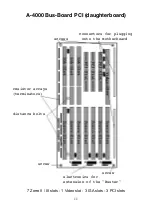
Now connect the power extension cable with the one side to the
motherboard and with the other side to the plug of the PSU. Fix the cable
extension with the two nylon cable ties onto the metal brace of the tower.
You can put the clutch of the extension cable into the brace.
At the motherboard plug of the cable extension are 3 pairs of cables. One
of them consits of 2 pins the other one of 4 pins. You have now to connect
them with the respective plugs. If you do so pay attention that you always
connect with conjuction of the wire color. The definition of the cable is as
follows:
Green / White
or
Black / White = + 5 V power supply of the MHz display
White / Blue = RESET
Red / Black = + 12 V power supply for the supplementary fan
Change the polarity of the 2 pin connector if the fan doesn't work.
If you want to use the PSU of the Classic Micronik A-4000 Tower, then
you have to use another fan cover (please order if not included). Take the
fan out of its old position and fix it onto the new fan cover. Now screw this
unit with four M3 screws to the second position from the top at the rear of
the tower. The PSU of the Classic Micronik A-4000 Tower is fixed to the
top position of the tower. In some cases you have to pay attention to
different threads. The power switch of the Classic MicroniK A-4000 Tower
PSU has to be fixed onto the metal sheet which is located behind the
power switch button.
The power switch of the original Commodore PSU is operated from the
front by a extension plastic rod. Put first the end of the plastic rod with no
slit into the back of the power switch button and then the other end with
the slit onto the switch of the original Commodore PSU. To fix the plastic
rod slid the bold till it fits correctly.
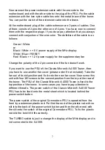
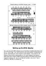
The TURBO switch is just to change the display of the MHz display and is
not connected to the A-4000.
7


