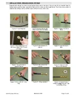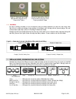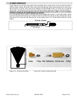
BIGHORN_March 2020.docx
March 26, 2020
Page
18 of 36
15.
INSTALLATION OF ATOMIZATION LINE
15.1
METHODS OF SUSPENDING ATOMIZATION LINES
The two basic methods used to mount and suspend atomization lines are
1. Stainless Steel Aircraft Cable.
2. Hose Mounting Clamps.
The type of structure and the location where the atomization lines will be installed determines the appropriate
method. Often a combination of methods is used.
15.2
USE OF AIRCRAFT CABLE
Aircraft Cable is 7 x 7 stranded 1/16” (0.31mm) stainless steel cable, rated at about 500 lbs. tensile strength. With
this method, the atomization line is attached using cable ties at approximately 12"(304mm) on-center. It is extremely
important that the cable be installed along the top of the atomization line with the cable tie snaps being placed on
the hose, not the cable. See figure 6.
The Aircraft Cable is strung between posts, columns or a fabricated structure that locates the atomization line in the
desired position. The cable is then drawn tight by a ratchet mechanism. This method allows atomization line to span
distances of up to 10 to 15 feet (3 to 5 MT) where there is lack of continuous support.
Typical situations where this method would be useful are fixing atomization line to structures of greenhouses, storage
houses, waste load-out facilities, perimeter fencing around sludge ponds or strung between poles to span across
sewage lagoons. The possibilities are numerous.
15.3
AIRCRAFT CABLE INSTALLATION TECHNIQUE
Special tools required: Aircraft Cable cutter & 1/16" Sleeve crimping tool.
(Aircraft cable tool kit MicroCool PART# TKT0003)
1. Select the two points from which you require your manifold line or atomization line to span. Points may be
existing structures such as roof beams, columns, etc. or fabricated poles that will allow cable to be wrapped
around.
2. If the points are on a wall or any other flat surface, eyelets will have to be fabricated to fix the ends of the cable.
Remember, to create a drainage gradient for the atomization lines, the points must not be level.
3. Pull one length of Aircraft Cable between the two points. Pull an extra 2 feet (0.61 M) and cut using the cable
cutter.
4. The Aircraft Cable ends are generally fixed by forming a loop and this is held using crimp sleeves. Please refer
to the following drawing.
Figure 4. – Fixing First End of Aircraft Cable
1. CRIMP SLEEVES SLIDE ONTO
& DOWN THE AIRCRAFT CABLE
3. END OF CABLE FED THROUGH
CRIMP SLEEVES
2. AIRCRAFT CABLE LOOPED AROUND POST
STRAINING POST
5. Take one end of the Aircraft Cable and pull it around the point in the above fashion. Use the crimping tool and
firmly crimp each sleeve three times along its length.
Содержание BIGHORN 1000
Страница 28: ...BIGHORN_March 2020 docx March 26 2020 Page 28 of 36 22 BIGHORN ILLUSTRATIONS...
Страница 29: ...BIGHORN_March 2020 docx March 26 2020 Page 29 of 36 22 1 BIGHORN FRONT EXTERNAL VIEW...
Страница 30: ...BIGHORN_March 2020 docx March 26 2020 Page 30 of 36 22 2 BIGHORN BACK EXTERNAL VIEW...
Страница 31: ...BIGHORN_March 2020 docx March 26 2020 Page 31 of 36 22 3 BIGHORN RIGHT EXTERNAL VIEW...
Страница 32: ...BIGHORN_March 2020 docx March 26 2020 Page 32 of 36 22 4 BIGHORN LEFT EXTERNAL VIEW...
Страница 33: ...BIGHORN_March 2020 docx March 26 2020 Page 33 of 36 22 5 BIGHORN TOP EXTERNAL VIEW...
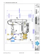
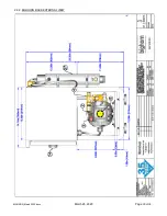
Страница 34: ...BIGHORN_March 2020 docx March 26 2020 Page 34 of 36 22 6 BIGHORN TOP INTERNAL VIEW...
Страница 35: ...BIGHORN_March 2020 docx March 26 2020 Page 35 of 36 22 7 BIGHORN CONTROL PANEL VIEW...
Страница 36: ...BIGHORN_March 2020 docx March 26 2020 Page 36 of 36 22 8 NOTES...

