


PIC16F716
DS41206A-page 66
Preliminary
2003 Microchip Technology Inc.
9.10
Interrupts
The PIC16F716 devices have up to 7 sources of
interrupt. The Interrupt Control Register (INTCON)
records individual interrupt requests in flag bits. It also
has individual and global interrupt enable bits.
A Global Interrupt Enable bit, GIE (INTCON<7>)
enables all un-masked interrupts when set, or disables
all interrupts when cleared. When bit GIE is enabled,
and an interrupt’s flag bit and mask bit are set, the
interrupt will vector immediately. Individual interrupts
can be disabled through their corresponding enable
bits in various registers. Individual interrupt bits are set,
regardless of the status of the GIE bit. The GIE bit is
cleared on Reset and when an interrupt vector occurs.
The “return-from-interrupt” instruction,
RETFIE
, exits
the interrupt routine, as well as sets the GIE bit, which
re-enables interrupts.
The RB0/INT pin interrupt, the RB port change interrupt
and the TMR0 overflow interrupt flags are contained in
the INTCON register.
The peripheral interrupt flags are contained in the
special function registers, PIR1 and PIR2. The
corresponding interrupt enable bits are contained in
special function registers, PIE1 and PIE2, and the
peripheral interrupt enable bit is contained in special
function register, INTCON.
When an interrupt is responded to, the GIE bit is
cleared to disable any further interrupt, the return
address is pushed onto the stack and the PC is loaded
with 0004h. Once in the interrupt service routine, the
source(s) of the interrupt can be determined by polling
the interrupt flag bits. The interrupt flag bit(s) must be
cleared in software before re-enabling interrupts to
avoid recursive interrupts.
For external interrupt events, such as the INT pin or
PORTB change interrupt, the interrupt latency will be
three or four instruction cycles. The exact latency
depends when the interrupt event occurs. The latency
is the same for one or two-cycle instructions. Individual
interrupt flag bits are set, regardless of the status of
their corresponding mask bit or the GIE bit.
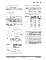
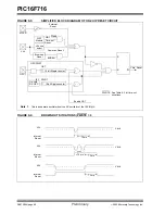
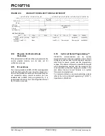
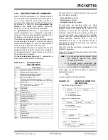
FIGURE 9-13:
INTERRUPT LOGIC
Note:
Individual interrupt flag bits are set regard-
less of the status of their corresponding
mask bit or the GIE bit.
ADIF
ADIE
CCP1IF
CCP1IE
TMR2IF
TMR2IE
TMR1IF
TMR1IE
T0IF
T0IE
INTF
INTE
RBIF
RBIE
GIE
PEIE
Wake-up (If in Sleep mode)
Interrupt to CPU
Содержание PIC16F716
Страница 6: ...PIC16F716 DS41206A page 4 Preliminary 2003 Microchip Technology Inc NOTES...
Страница 35: ......
Страница 56: ......
Страница 60: ......
Страница 88: ......
Страница 92: ...PIC16F716 DS41206A page 90 Preliminary 2003 Microchip Technology Inc NOTES...
Страница 108: ...PIC16F716 DS41206A page 106 Preliminary 2003 Microchip Technology Inc NOTES...
Страница 110: ...PIC16F716 DS41206A page 108 Preliminary 2003 Microchip Technology Inc NOTES...
Страница 124: ...PIC16F716 DS41206A page 122 Preliminary 2003 Microchip Technology Inc NOTES...


