


Installation and Operation
2013 Microchip Technology Inc.
DS20005196A-page 15
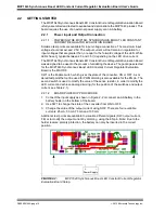
2.2.1.3
ADJUSTABLE LED CURRENT SETTING BY RECALCULATING THE
SENSE RESISTOR
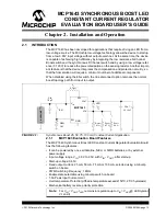
The Sense Resistor is used to modify the value of the output current. The value for the
sense resistor can be calculated using the following equation:
R
2
= V
FB
/I
LED
Where: V
FB
= 0.120V
2.2.1.4
ADJUSTABLE LED CURRENT SETTING BY USING THE EN PIN (PWM
DIMMING)
The MCP1643 allows PWM dimming by turning the LED ON or OFF with a variable
duty cycle PWM signal applied to the EN pin. The maximum frequency for dimming is
limited by the internal soft-start of 240 µs typical. By varying the duty cycle of the PWM
signal applied on EN input, the LED current is changing linearly and the light intensity
changes as well.
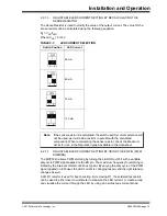
A 0
Ω
R1 resistor is used for bench testing. By removing R1, the soldered test points
can be used to either insert a multimeter to measure the LED current, or create a loop
and visualize the current through the LED by using an oscilloscope current probe.
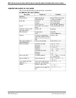
TABLE 2-1:
LED CURRENT SELECTION
Switch Position
LED Current
25 mA
50 mA
75 mA
100 mA
ON
2
1
ON
2
1
ON
2
1
ON
2
1
Note:
If the sense resistor is recalculated, the switch used for current selection will
not be used, as it will add a resistor in parallel with the calculated
component. When recalculating the sense resistor, check the Maximum
Limits for I
LED
in the Regulation graph available in the data-sheet.


