4.
Hardware Specifications
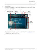
This chapter describes the connectors and header of the ATWILC 3000 Shield board.
4.1
ATWILC3000 Shield Arduino Shield Stacking Connectors
The ATWILC3000 Shield contains Arduino shield stacking connectors, which are used to connect the
board to an MCU base board. This is also used to expose the unused pins to the user. The pinout
definition for the shield connectors are given in the following tables.
Table 4-1. J200 Stacking Connector
Pin Number
Function
Description
1
SD_DAT2
SDIO Data 2
2
SD_DAT1
SDIO Data 1
3
SPI_SS
SPI select. By default, this pin is not connected. Mount
R217 (0Ω) to connect.
4
SPI_MOSI
SPI MOSI. By default, this pin is not connected. Mount
R216 (0Ω) to connect.
5
SPI_MISO
SPI MISO. By default, this pin is not connected. Mount
R215 (0Ω) to connect.
6
SPI_SCK
SPI Clock. By default, this pin is not connected. Mount
R214 (0Ω) to connect.
7
GND
Ground
8
NC
Not connected
9
NC
Not connected
10
NC
Not connected
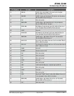
Table 4-2. J201 Stacking Connector
Pin Number
Function
Description
1
NC
Not connected
2
NC
Not connected
3
NC
Not connected
4
VCC_INT_P3V3
3.3V power supply. Mount jumper cap on J300-1 and
J300-2 to use this supply.
5
NC
Not connected
6
GND
Ground
7
GND
Ground
8
NC
Not connected
ATWILC3000
Hardware Specifications
©
2018 Microchip Technology Inc.
User Guide
DS50002769A-page 7

