


9.
Hardware Flow Control for 4-Wire Mode eFuse Write Procedure
This procedure is applicable only for the MR/CSP/QFN packages. The ATBTLC1000-ZR module comes with a 4-wire
mode eFuse by default from the factory.
CAUTION
While writing data to the eFuse, the data written can never be changed (that is, if a value of '1' is written to
a specific eFuse, those contents can never be reverted back to its original value). To configure the eFuse
controller for accessing the eFuse contents, the user must enter the valid arguments for eFuse
configuration.
1.
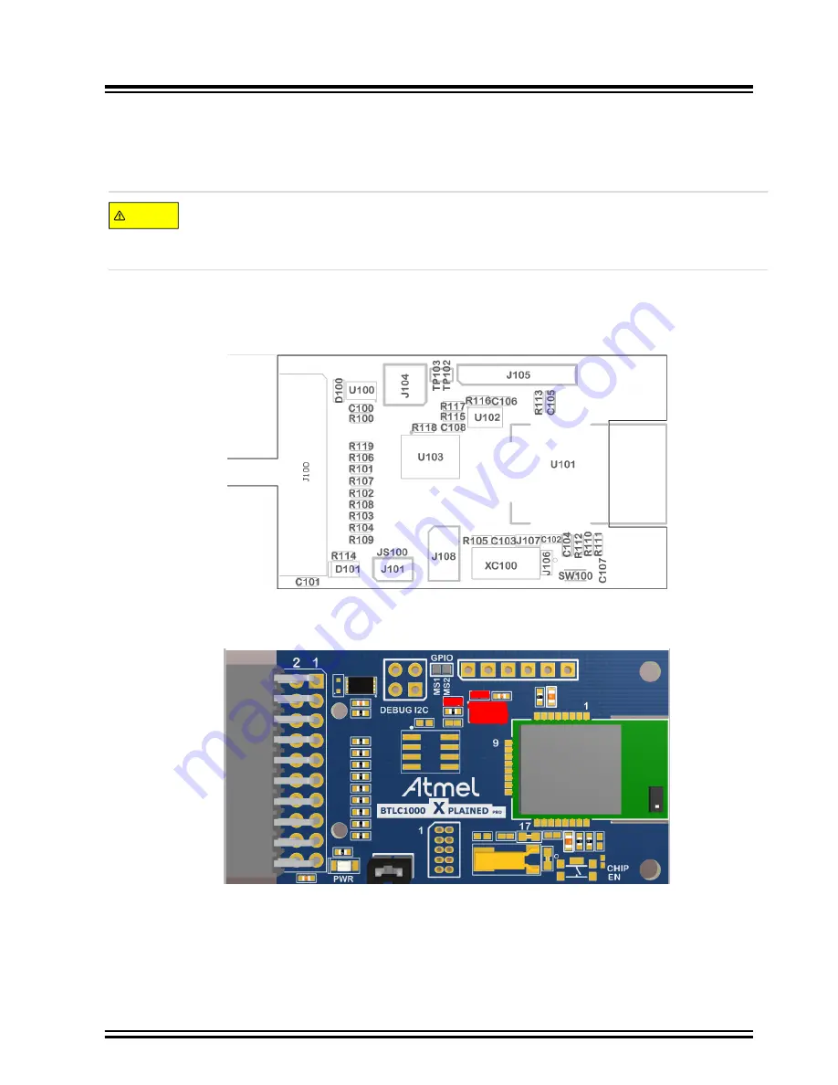
Connect the SAM-ICE to the J108 header and the ATBTLC1000 XPRO to any MCU board to power it up. For
the J108 location, refer to the following assembly drawing. Ensure that the “ATBTLC1000 chip enable” and
“Wakeup pin” are driven high throughout the eFuse process.
Figure 9-1. ATBTLC1000 XPRO Board Assembly Diagram
2.
Remove pins U102, R116, and R117 on the ATBTLC1000 XPRO to disconnect the temperature sensor chip
from the GPIOs used for flow control, as shown in following figure (highlighted in red).
Figure 9-2. ATBTLC1000 3D View XPRO Board
3.
The supplied command line tool (
EfuseBlockProgram.exe
) is used to write the ATBTLC1000 eFuse to
configure the flow control signals.
4.
To invoke the help information from the EfuseBlockProgram, enter
EfuseBlockProgram.exe -h
in the
command line.
ATBTLC1000
Hardware Flow Control for 4-Wire Mode eFuse ...
©
2019 Microchip Technology Inc.
User Guide
DS50002640B-page 78