Troubleshooting
continued
RFT9739 Rack-Mount Transmitter Instruction Manual
77
Be
fo
re
Y
o
u
B
e
g
in
Getti
ng Sta
rted
M
oun
ting
P
o
w
e
r-
Suppl
y and
Sen
s
or Wi
ri
ng
O
u
tp
ut Wi
ri
ng
Star
tu
p
T
ro
u
b
le
s
hoo
ting
7.5
Power supply
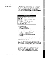
The transmitter is configured at the factory for a 110/115 VAC or
220/230 VAC power supply. All RFT9739 rack-mount transmitters can
accept a 12 to 30 VDC power supply, independent of the AC power-
supply configuration.
• A label on the upper corner of the transmitter back panel indicates the
configured power-supply voltage.
• The AC power supply voltage configuration can be changed by the
user. See Section 4.3, page 21.
Check for specified power at the transmitter terminals.
• Wire DC power at connector CN2, to terminals Z32 (DC+) and
D32 (DC–).
• Wire AC power at connector CN3 and the ground lug above connector
CN3.
• Some European applications require installation of AC power-supply
wiring to connector CN2, terminals D2 (AC+), D6 (AC–), and
Z2 (GND).
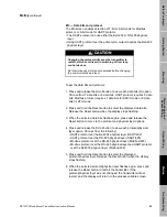
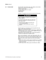
In Europe, before making AC power-supply wiring
connections at CN2,
contact the Micro Motion Customer Service
Department. In Europe, phone +31 (0) 318 549 443.
• If the transmitter is wired for an AC power supply, ensure switch S1 on
the power board is in the appropriate position. See Section 4.3,
page 21.
• Check fuses. See "Fuses", page 21.
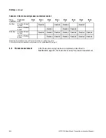
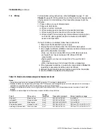
Table 7-5. Using informational messages
Message
Condition
Corrective action(s)
Power Reset
• Power failure
• Brownout
• Power cycling
Check accuracy of totalizers
Cal in Progress
• Flowmeter zeroing in progress
• Density calibration in progress
• If Cal in Progress disappears, no action
• If Cal in Progress reappears after zeroing or
calibration is completed:
- Check flowmeter cable
- Eliminate noise, then rezero or recalibrate
Zero Too Noisy
Mechanical noise prevented accurate zero
flow setting during auto zero
Eliminate mechanical noise, if possible, then rezero
Zero Too High
Zero Too Low
Flow not completely shut off during auto zero
Completely shut off flow, then rezero
Moisture in sensor junction box caused zero
drift
Ensure interior of junction box is completely dry, then
rezero
Burst Mode
Transmitter configured to send data in burst
mode under HART protocol
Switch burst mode OFF
mA 1 Fixed
Communication failure during test or trim of
mA output from terminals CN2-Z30 (PV+)
and CN2-D30 (PV–)
Complete trim or test
Polling address of 1 to 15 assigned to
RFT9739 for HART in Bell 202
• Change polling address to zero (0)
• Use RS-485 communication standard
mA 2 Fixed
Communication failure during test or trim of
output from terminals CN2-Z28 (SV+) and
CN2-D28 (SV–)
Complete trim or test
Event 1 On
Event (alarm) 1 is ON
• If totalizer assigned:
- Low alarm switches event ON at totalizer reset
- High alarm switches event OFF at totalizer reset
• If other variable assigned, event switches ON/OFF
when variable crosses setpoint
Event 2 On
Event (alarm) 2 is ON
Security Breach
Security mode changed from mode 8
• Re-enter security mode 8
• Perform master reset
Содержание Fisher Rosemount RFT9739
Страница 1: ...Model RFT9739 Rack Mount Transmitter Instruction Manual Version 3 Transmitters February 2000 ...
Страница 2: ......
Страница 4: ......
Страница 20: ...10 RFT9739 Rack Mount Transmitter Instruction Manual ...
Страница 26: ...16 RFT9739 Rack Mount Transmitter Instruction Manual ...
Страница 92: ...82 RFT9739 Rack Mount Transmitter Instruction Manual ...
Страница 100: ...90 RFT9739 Rack Mount Transmitter Instruction Manual ...
Страница 110: ...100 RFT9739 Rack Mount Transmitter Instruction Manual ...
Страница 112: ...102 RFT9739 Rack Mount Transmitter Instruction Manual ...
Страница 120: ...110 RFT9739 Rack Mount Transmitter Instruction Manual ...
Страница 122: ...112 RFT9739 Rack Mount Transmitter Instruction Manual ...
Страница 129: ......

