


10.2
Commissioning Tests
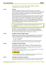
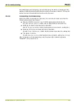
10.2.1
Preparation
After the P631 has been installed and connected as described in Chapter
“Installation and Connection”, the commissioning procedure can begin.
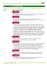
Before turning on the power supply voltage, the following items must be checked
again:
●
Is the device connected to the protective ground at the specified location?
●
Does the nominal voltage of the battery agree with the nominal auxiliary
voltage of the device?
●
Are the current and voltage transformer connections, grounding, and phase
sequences correct?
After the wiring work is completed, check the system to make sure it is properly
isolated. The conditions given in VDE 0100 must be satisfied.
Once all checks have been made, the power supply voltage may be turned on.
After voltage has been applied, the device starts up. During startup, various
startup tests are carried out (see
). The LED indicators for
HEALTHY (H1) and OUT OF SERVICE (H2) will light up. After approximately 15 s,
the P631 is ready for operation. By default (factory setting) or after a cold restart,
the device type “P631” and the time are displayed on the first line of the LCD
after the device has started up.
Once the change enabling command has been issued (see
), all settings can be entered. The procedure for entering settings from the
integrated local control panel is described in
.
If either the PC interface or the communication interface will be used for setting
the P631 and reading out event records, then the following settings must first be
made from the integrated local control panel.
Par/DvID menu branch:
●
DVICE: Device password 1
●
DVICE: Device password 2
10 Commissioning
P631
P631/EN M/R-11-C // P631-310-650
10-3
Содержание P631
Страница 2: ......
Страница 4: ......
Страница 7: ...Changes after going to press...
Страница 8: ......
Страница 16: ...P631 Table of Contents 8 P631 EN M R 11 C P631 310 650...
Страница 56: ...P631 2 Technical Data 2 28 P631 EN M R 11 C P631 310 650...
Страница 236: ...P631 3 Operation 3 180 P631 EN M R 11 C P631 310 650...
Страница 246: ...P631 4 Design 4 10 P631 EN M R 11 C P631 310 650...
Страница 266: ...P631 5 Installation and Connection 5 20 P631 EN M R 11 C P631 310 650...
Страница 276: ...6 8 Configurable Function Keys P631 6 Local Control HMI 6 10 P631 EN M R 11 C P631 310 650...
Страница 548: ...P631 10 Commissioning 10 10 P631 EN M R 11 C P631 310 650...
Страница 568: ...P631 12 Maintenance 12 8 P631 EN M R 11 C P631 310 650...
Страница 570: ...P631 13 Storage 13 2 P631 EN M R 11 C P631 310 650...
Страница 572: ...P631 14 Accessories and Spare Parts 14 2 P631 EN M R 11 C P631 310 650...
Страница 576: ...P631 15 Order Information 15 4 P631 EN M R 11 C P631 310 650...
Страница 582: ...P631 A2 Internal Signals A2 4 P631 EN M R 11 C P631 310 650...
Страница 608: ...P631 A4 Telecontrol Interfaces A4 18 P631 EN M R 11 C P631 310 650...
Страница 637: ......


