


5.5
Protective and Operational Grounding
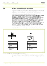
The device must be reliably grounded to meet protective equipment grounding
requirements. The surface-mounted case is grounded using the bolt and nut,
appropriately marked, as the ground connection. The flush-mounted case must
be grounded in the area of the rear sidepieces at the location provided.
The bracket is marked with the protective ground symbol:
The cross-section of the ground conductor must conform to applicable national
standards. A minimum cross section of 2.5 mm² (
≤
AWG12) is required.
In addition, a protective ground connection at the terminal contact on the power
supply module (identified by the letters “PE” on the terminal connection
diagram) is also required for proper operation of the device. The cross-section of
this ground conductor must also conform to applicable national standards. A
minimum cross section of 1.5 mm² (US:
AWG14 or thicker) is required.
If a detachable HMI is installed, a further protective conductor (ground/earth) of
at least 1.5 mm² (US:
AWG14 or thicker) must be connected to the DHMI
protective conductor terminal to link the DHMI and the main relay case; these
must be located within the same substation.
All grounding connections must be low-inductance, i.e. it must be kept as short
as possible.
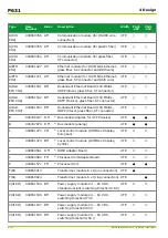
19Y5220B
1
2
3
4
1
2
3
4
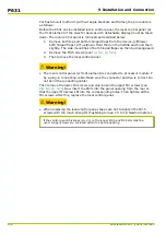
PE terminal
Description
Nut M4
Bolt M4
Clamp bracket
Tooth lock wash.A4.3
surface-mount. case
PE terminal
Description
Nut M4
Bolt M4
Clamp bracket
Tooth lock wash.A4.3
flush-mount. case
Pos.
1
2
3
4
Pos.
1
2
3
4
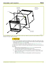
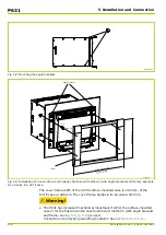
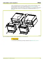
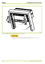
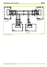
Fig. 5-8: Installing the protective grounding conductor terminal.
The protective conductor (earth) must always be connected to the protective
grounding conductor terminal in order to guarantee the safety given by this set-
up.
5 Installation and Connection
P631
P631/EN M/R-11-C // P631-310-650
5-11
Содержание P631
Страница 2: ......
Страница 4: ......
Страница 7: ...Changes after going to press...
Страница 8: ......
Страница 16: ...P631 Table of Contents 8 P631 EN M R 11 C P631 310 650...
Страница 56: ...P631 2 Technical Data 2 28 P631 EN M R 11 C P631 310 650...
Страница 236: ...P631 3 Operation 3 180 P631 EN M R 11 C P631 310 650...
Страница 246: ...P631 4 Design 4 10 P631 EN M R 11 C P631 310 650...
Страница 266: ...P631 5 Installation and Connection 5 20 P631 EN M R 11 C P631 310 650...
Страница 276: ...6 8 Configurable Function Keys P631 6 Local Control HMI 6 10 P631 EN M R 11 C P631 310 650...
Страница 548: ...P631 10 Commissioning 10 10 P631 EN M R 11 C P631 310 650...
Страница 568: ...P631 12 Maintenance 12 8 P631 EN M R 11 C P631 310 650...
Страница 570: ...P631 13 Storage 13 2 P631 EN M R 11 C P631 310 650...
Страница 572: ...P631 14 Accessories and Spare Parts 14 2 P631 EN M R 11 C P631 310 650...
Страница 576: ...P631 15 Order Information 15 4 P631 EN M R 11 C P631 310 650...
Страница 582: ...P631 A2 Internal Signals A2 4 P631 EN M R 11 C P631 310 650...
Страница 608: ...P631 A4 Telecontrol Interfaces A4 18 P631 EN M R 11 C P631 310 650...
Страница 637: ......


