


3.26
Measuring-Circuit Monitoring (Function Groups MCM_1 and
MCM_2)
The measuring-circuit monitoring function featured by the P631 will detect faults
in the secondary circuits of the CTs. Measuring-circuit monitoring functions
MCM_1 and MCM_2 are permanently assigned to the transformer ends monitored
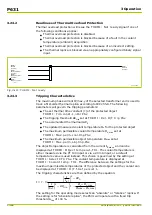
by the P631.
Function group MCM_1 will serve as an example to illustrate the operation of the
measuring-circuit monitoring functions. The same will apply to function group
MCM_2.
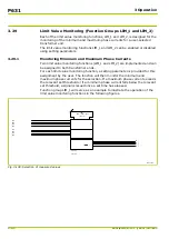
3.26.1
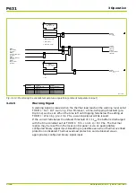
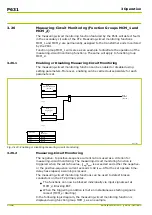
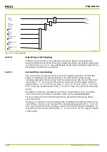
Enabling or Disabling Measuring-Circuit Monitoring
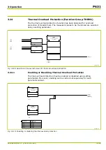
The measuring-circuit monitoring function can be enabled or disabled using
setting parameters. Moreover, enabling can be carried out separately for each
parameter set.
64Z5186A
Parameter
set 1
set 2
set 3
set 4
MCM_1:
Enable PSx
081 038
082 038
083 038
084 038
MCM_1:
Enabled
[ 036 194 ]
MCM_1:
Enable PSx
[ * ]
1
0
0: No
1: Yes
0
0: No
1: Yes
MCM_1:
General enable USER
[ 031 146 ]
1
Fig. 3-123: Enabling or disabling measuring-circuit monitoring
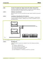
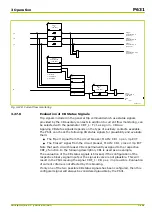
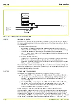
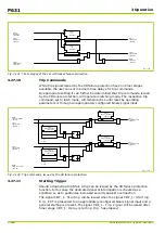
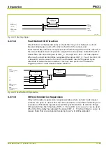
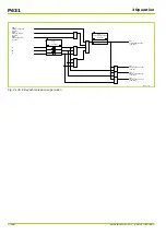
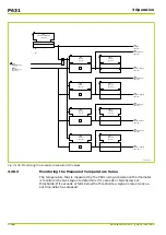
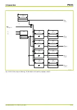
3.26.2
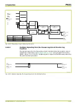
Measuring-Circuit Monitoring
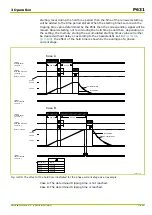
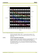
The negative- to positive-sequence current ratio is used as a criterion for
measuring-circuit monitoring. The measuring-circuit monitoring function is
triggered when the set ratio value, I
neg
/I
pos
, is exceeded and either the negative-
or the positive-sequence current exceeds 0.02 I
nom
. After the set operate time-
delay has elapsed, a warning is issued.
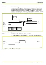
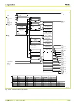
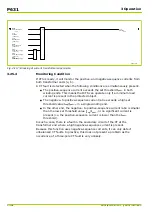
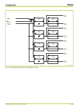
The measuring-circuit monitoring functions can be used to detect broken
conductors on the CTs' primary sides.
●
The functions can now be blocked individually via input signals set at
MCM_x: Blocking EXT.
●
When the triggering condition is met an instantaneous starting signal is
raised: (MCM_x: Starting).
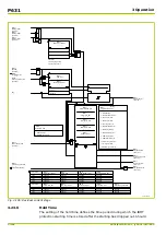
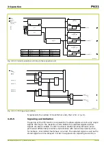
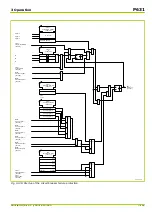
In the following logic diagram, the measuring-circuit monitoring function is
displayed using function group MCM_1 as an example.
P631
3 Operation
3-156
P631/EN M/R-11-C // P631-310-650
Содержание P631
Страница 2: ......
Страница 4: ......
Страница 7: ...Changes after going to press...
Страница 8: ......
Страница 16: ...P631 Table of Contents 8 P631 EN M R 11 C P631 310 650...
Страница 56: ...P631 2 Technical Data 2 28 P631 EN M R 11 C P631 310 650...
Страница 236: ...P631 3 Operation 3 180 P631 EN M R 11 C P631 310 650...
Страница 246: ...P631 4 Design 4 10 P631 EN M R 11 C P631 310 650...
Страница 266: ...P631 5 Installation and Connection 5 20 P631 EN M R 11 C P631 310 650...
Страница 276: ...6 8 Configurable Function Keys P631 6 Local Control HMI 6 10 P631 EN M R 11 C P631 310 650...
Страница 548: ...P631 10 Commissioning 10 10 P631 EN M R 11 C P631 310 650...
Страница 568: ...P631 12 Maintenance 12 8 P631 EN M R 11 C P631 310 650...
Страница 570: ...P631 13 Storage 13 2 P631 EN M R 11 C P631 310 650...
Страница 572: ...P631 14 Accessories and Spare Parts 14 2 P631 EN M R 11 C P631 310 650...
Страница 576: ...P631 15 Order Information 15 4 P631 EN M R 11 C P631 310 650...
Страница 582: ...P631 A2 Internal Signals A2 4 P631 EN M R 11 C P631 310 650...
Страница 608: ...P631 A4 Telecontrol Interfaces A4 18 P631 EN M R 11 C P631 310 650...
Страница 637: ......


