MICO aeronom WR 600 Скачать руководство пользователя страница 1


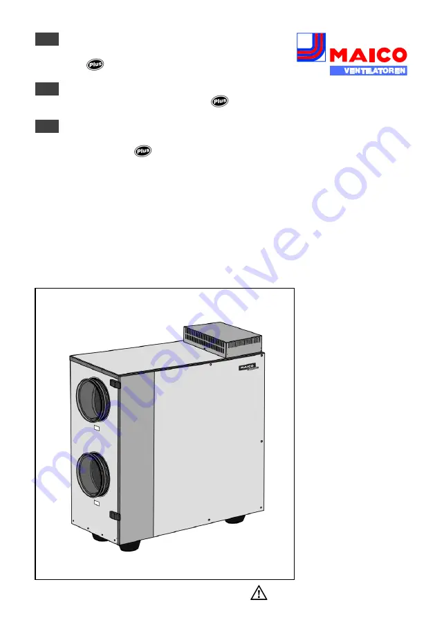
Montage- und Betriebsanleitung


Wärmerückgewinnungssystem 

mit        -Funktion 


Mounting and Operating instructions


Heat Recovery System with 

      -Function 


Instructions de montage et Mode d’emploi


Système de récupération de chaleur 

avec Fonction  


aeronom 


WR 600 

w w w . m a i c o - v e n t i l a t o r e n . c o m  


DE 


EN 

FR 

Содержание aeronom WR 600

Страница 1: ...winnungssystem mit Funktion Mounting and Operating instructions Heat Recovery System with Function Instructions de montage et Mode d emploi Syst me de r cup ration de chaleur avec Fonction aeronom WR...

Страница 2: ...50 W rmer ckgewinnungssystem mit Funktion Mounting and Operating instructions Page 51 100 Heat Recovery System with Function Instructions de montage et Mode d emploi Page 101 151 Syst me de r cup rat...

Страница 3: ...alter bauseitig 9 4 Sicherheitshinweise 9 4 1 Allgemein 9 4 2 Bestimmungsgem e Verwendung 10 4 3 Vorhersehbare Fehlanwendungen 11 4 4 Bestimmungen f r den Betrieb mit Feuerst tten 11 4 4 1 L ftungstec...

Страница 4: ...t 21 8 2 Anforderungen an den Aufstellungsort 21 9 Installation Fachinstallateur 22 9 1 Vorgehensweise 22 9 2 L ftungsger t aufstellen 22 9 3 Schallschutz 23 9 4 Kondensatabfluss 24 9 5 L ftungskan le...

Страница 5: ...ln aufgefordert F hren Sie die angegebenen Anweisungen der Reihe nach aus 3 Produktinformationen WR 600 L ftungssysteme mit W rmer ck gewinnung werden zur kontrollierten Wohnungsl ftung eingesetzt Ver...

Страница 6: ...4...

Страница 7: ...rontt r 2 1 ge ffnet wird 8 Luftfilter Filterklasse G4 Filtert grobe Verun reinigungen aus Au en und Abluft Pos Bezeichnung Funktion 9 W rme tauscher Im W rmetauscher erfolgt die W rme bertragung zwis...

Страница 8: ...entemperaturen Ein Frostschutz Temperaturf hler berpr ft st ndig die Temperatur am W rme tauscher Der Zuluftventilator schaltet aus wenn die Temperatur am W rmetauscher unter den eingestellten Frosts...

Страница 9: ...it und ein geeignetes Filterkonzept geachtet werden unbedingt auch eine Revisions ffnung vorsehen Das L ftungsger t l sst sich auch zusam men mit KNX EIB Bus Komponenten betreiben zum Beispiel mit Fan...

Страница 10: ...O2 Sensor Option Sensor zur Erfassung von Kohlendioxid CO2 Der CO2 Gehalt der Luft gilt als Indikator f r die Raumluftqualit t Je gr er der CO2 Gehalt desto schlechter die Raumluft Das L ftungsger t r...

Страница 11: ...m Rauch fr hzeitig zu erkennen und das Ausbreiten innerhalb von Wohneinheiten durch das L ftungssystem zu verhindern Der Rauchschalter schaltet im Bedarfsfall die Ventiltoren im L ftungsger t ab Beach...

Страница 12: ...Montage ist nur durch autorisierte Fachkr fte zul ssig Elektrischer Anschluss und Reparaturen sind nur durch Elektrofachkr fte zul ssig Betreiben Sie das L ftungs ger t nur mit auf dem Typenschild ang...

Страница 13: ...it Labor absaugungen in Kombination mit Dunst abzugshauben die direkt am Abluftkanal der kontrollierten Wohnungsl ftung angeschlos sen sind Nicht zul ssig ist die Ein bindung von Komponenten im Abluft...

Страница 14: ...mluftabh ngigen Feuer st tten f r feste Brennstoffe muss im Ausl sefall der Sicherheitseinrichtung die L ftungsanlage abgeschaltet werden Zentrale L ftungsger te aeronom WR 600 zur kontrollierten Be u...

Страница 15: ...rhindern siehe Kapitel 9 6 5 Anschlussvariante 8 4 5 Bestimmungen zur Erf llung der Passivhaus kriterien 4 5 1 Frostschutzeinrichtung f r den W rme bertr ger Zur Gew hrleistung einer Dauerl ftung muss...

Страница 16: ...vl ftung Niedrigere L ftungsstufe Dr cken Sie Taste so oft bis die LED der gew nschten L ftungsstufe leuchtet Das L ftungsger t schaltet jeweils eine Stufe zur ck L ftungsstufe 3 L ftungsstufe 2 L ftu...

Страница 17: ...l ftung oder Intensivl ftung LED 1 blinkt regelm ig in kurzen Abst nden Intervallbetrieb L ftung zum Feuchte schutz LED Bedeutung LED der angew hlten L ftungsstufe blinkt regel m ig in l ngeren Abst n...

Страница 18: ...Metallrahmen mit Luftfilter 1 und 2 aus dem L ftungsger t Nehmen Sie die Filtereinlagen aus den Metallrahmen heraus Entsorgen Sie diese gem den rtlichen Bestimmungen Reinigen Sie die Metallrahmen mit...

Страница 19: ...ab Ziehen Sie den W rmetauscher vorsichtig und parallel mit beiden Griffen aus dem L ftungsger t heraus ACHTUNG Dichtstreifen beim Heraus ziehen Einschieben des W rmetauschers nicht besch digen L ftun...

Страница 20: ...ftungsger tes 7 St rungen Meldungen 7 1 Filterwechselanzeige An Raumluftsteuerung RLS 1 WR blinkt die LED der angew hlten L ftungsstufe regelm ig in l ngeren Abst nden An Raumluftsteuerung RLS D1 WR w...

Страница 21: ...ndig an den Klemmenpaaren und der Steuerplatine A2 s Kap 9 6 Elektrischer Anschluss an GEFAHR Lebensgefahr durch Strom schlag Ber hren Sie niemals span nungsf hrende Teile Pr fen Sie die abluft und zu...

Страница 22: ...1 V an den Steckerpins an Vor der Messung die St rungsmeldung gem Kapitel 7 2 1 l schen Zuluft und abluft seitig die Vorgabe spannung gem Kapitel 7 2 2 messen Diese muss 1 10 V DC betragen Ggf Steuer...

Страница 23: ...cherung pr fen Frontabdeckung pr fen 8 Installationsvorbereitungen 8 1 Transport Das L ftungsger t wird auf einer Palette angeliefert Halten Sie f r den Transport g ltige Sicherheits und Unfallverh tu...

Страница 24: ...rden Ber cksichtigen Sie die Planungsunter lagen des Planungsb ros und die in Ihrem Land geltenden Bestimmungen Ber cksichtigen Sie die Technischen Daten in Kapitel 12 Schlie en Sie vor dem Einbau all...

Страница 25: ...3 Schallschutz Die Schallemissionen durch die L ftungs anlage sind von vielen Faktoren abh ngig zum Beispiel Geb udebauweise L ftungs komponenten usw F hren Sie die L ftungsanlage deshalb entsprechen...

Страница 26: ...en tigt eine Sperrwasserh he von min 50 mm Installieren Sie zur Aufnahme des Kondensats an die Kanalisation einen offenen Tropftrichter mit einem weiteren Siphon So ist das L ftungsger t von der Kanal...

Страница 27: ...an der Au enseite des Fortluft und Au enluftkanals zu verhindern Die D mmung der Rohrleitungen muss nach den bestehenden Regeln der Technik ausgef hrt werden Kleben Sie die Sto stellen gut ab entkoppe...

Страница 28: ...26 Anschl sse und Abmessungen A Anschlussstutzen Au enluft B Anschlussstutzen Abluft C Anschlussstutzen Zuluft D Anschlussstutzen Fortluft E Elektroanschluss F Kondensatabfluss...

Страница 29: ...durch Gegenst nde in den L ftungs kan len Installieren Sie zuerst das L ftungsger t mit allen Zu und Abluftkan len Schlie en Sie erst dann das L ftungsger t elektrisch an ACHTUNG Besch digung durch Be...

Страница 30: ...Sie die Netzsicherung aus Bringen Sie ein Warnschild gegen verse hentliches Wiedereinschalten sichtbar an ffnen Sie den Elektro Anschlusskasten gem Kapitel 9 6 1 Verdrahten Sie die Leitungen gem eine...

Страница 31: ...en Au entemperaturen Ein Temperaturf hler berpr ft st ndig die Temperatur am W rmetauscher Sinkt die Fortluft Temperatur nach dem W r metauscher unter den vorgegebenen Frost schutz Ausschaltwert T Aus...

Страница 32: ...euerungen darf kein CO2 oder VOC Sensor ange schlossen sein A Elektro Anschlusskasten WR 600 A2 Steuerplatine Jumper 8 gebr ckt Werkseinstellung B1 1 Raumluftsteuerung RLS 1 WR B2 2 Raumluftsteuerung...

Страница 33: ...er 8 gebr ckt Werkseinstellung B Raumluftsteuerung RLS D1 WR W1 Anschlusskabel 230 VAC W2 Geschirmte Steuerleitung bauseitig f r Raumluftsteuerung RLS D1 WR Au endurchmesser 3 2 6 5 mm z B LIYCY 2 x 0...

Страница 34: ...R alternativ zu RLS D1 WR H1 Anzeigeelement zum Beispiel Glimmlampe bauseitig W1 Anschlusskabel 230 VAC W2 Geschirmte Steuerleitung bauseitig f r Raumluftsteuerung RLS D1 WR W2 Steuerleitung bauseitig...

Страница 35: ...bauseitig Au endurchmesser 3 2 6 5 mm z B LIYY 3 x 0 5 mm Anschluss auf Steuerplatine A2 an Klemmen CO2 und OT Zum Frei schalten Jumper 10 CO2 setzen siehe Abbildung Anschluss eines CO2 oder Luftqual...

Страница 36: ...ung RLS D1 WR B1 Raumluftsteuerung RLS 1 WR alternativ zu RLS D1 WR r F Hygrostat HY 5 oder HY5I siehe Zubeh r Wenn Sie L ftungsstufe 3 von Hand in Stufe 2 oder 1 zur ckschalten ist die Automatik funk...

Страница 37: ...ydraulisches Heizregister Nachheizregister WRH muss mit einer Sicherheitseinrichtung vor Frostsch den gesch tzt werden Zugeh rigen Temperaturf hler R1 unbedingt vor dem Wasserlufterhitzer WRH montiere...

Страница 38: ...ie die Abschalttemperatur auf 5 C und Differenz temperatur auf 3 K ein Anschluss Thermostat TH 10 Anschlusskabel bauseitig an Kabelver schraubung W3 entsprechend Verdrah tungsplan verdrahten Zuvor bra...

Страница 39: ...sstufe 1 S2 blau Potentiometer Stellrad L ftungsstufe 2 S3 blau Potentiometer Stellrad L ftungsstufe 3 Abluft S1 rot Potentiometer Stellrad L ftungsstufe 1 S2 rot Potentiometer Stellrad L ftungsstufe...

Страница 40: ...einzustellen Anschlussschema WR 600 L ftungsger t AB Abluft AU Au enluft ZU Zuluft FO Fortluft R1 Temperaturf hler S1 F hler Luftstromw chter Elektro Lufterhitzer Vorheizregister DRH 25 6 Standard ER...

Страница 41: ...ro Lufterhitzer zu installieren Temperaturf hler R1 des TH 10 ist in Str mungsrichtung min 50 cm nach dem Elektro Lufterhitzer zu installieren Um den Elektro Lufterhitzer vor Verschmut zung zu sch tze...

Страница 42: ...ischen Daten des Schaltausgangs potentialfreier Relaiskontakt k achten Mindestschaltleistung 230 VAC 2 A Die Verbindung zwischen Differenzdruck w chter Rauchschalter und L ftungsger t erfolgt mit Ansc...

Страница 43: ...und ffnen Sie die Frontt r Entfernen Sie die Frontabdeckung 7 Schrauben siehe Kapitel 6 3 1 Ziehen Sie den W rmetauscher vorsichtig und parallel mit beiden Griffen aus dem L ftungsger t heraus ACHTUN...

Страница 44: ...es Elektro Anschlusskastens Schwenken Sie die Abdeckung nach oben Stellen Sie an den 6 Potentiometer Stell r dern der Steuerplatine die Gesamt Volumenstr me der einzelnen L ftungs stufen ein f r Einst...

Страница 45: ...en in jeder L ftungsstufe von 1 10 V frei w hlbar Der Messvorgang der Steuerspannung ist im nachfolgenden Kapitel 10 4 Volumenstrom einstellungen mit Voltmeter beschrieben F r den erweiterten Einstell...

Страница 46: ...nschten Volumenstrom k nnen Sie der Tabelle in Kapitel 10 3 entnehmen Vorgabespannung f Volumenstrom Blaues Stellrad S1 f r die Vorgabespannung der L ftungsstufe 1 Blaues Stellrad S2 f r die Vorgabesp...

Страница 47: ...rdw rmetauscher oder ein hydraulisches Heizregister WRH TH 10 siehe Anschlussplan des Heizregisters oder einen Elektro Lufterhitzer DRH 25 6 LW 9 TH 10 US 16 T siehe Anschlussvariante 7 in Kapitel 9 6...

Страница 48: ...en Bemessungs spannung 230 VAC Netzfrequenz 50 Hz oder 60 Hz L ftungsstufen Werkseinstellung Reduzierte L ftung 230 m h Intervallbetrieb 56 der reduzierten L ftung Nennl ftung 345 m h Intensivl ftung...

Страница 49: ...WSG 600 1 4x Filterklasse G4 0093 0688 9 Ersatzluftfilter WSF 600 1 0093 0689 4x Filterklasse G4 1x Filterklasse F7 10 Ventilator DD 160 160 250 W 0156 0126 0000 11 W rmetauscher 0192 0507 9000 12 Te...

Страница 50: ...48 15 Anhang Verdrahtungsplan...

Страница 51: ...2 S3 rot Potentiometer Stellrad L ftungsstufe 3 Jumpereinstellungen J 1 3 Ger tetyp 011 WR 600 J 4 5 Frostschutztemperatur J 6 Keine Funktion J 7 Zeitbegrenzung 60 Minuten LS3 ist aktiviert J 8 Raumlu...

Страница 52: ...50...

Страница 53: ...by the customer 59 3 2 10 Smoke switch to be supplied by customer 59 4 Safety instructions 59 4 1 General 59 4 2 Intended use 60 4 3 Predictable misuses 61 4 4 Regulations for operation with fireplace...

Страница 54: ...2 Requirements at the installation site 71 9 Installation Specialist installer 72 9 1 Procedure 72 9 2 Installing the ventilation unit 72 9 3 Sound insulation 73 9 4 Condensation run off 74 9 5 Conne...

Страница 55: ...3 Product information WR 600 ventilation systems with heat recovery are used for controlled domestic ventilation Used air in the living area is transported to the outside and heat is extracted from it...

Страница 56: ...54 Exhaust air Supply air Outgoing air Outside air...

Страница 57: ...opened 8 Air filter filter class G4 Filters coarse dirt out of the outside air and exhaust air Item Designation Function 9 Heat exchanger The heat transfer between the exhaust air and supply air flow...

Страница 58: ...ures A frost protection temperature sensor monitors the temperature at the heat exchanger permanently The supply air fan switches off if the temperature at the heat exchanger falls below the preset fr...

Страница 59: ...to good cleanability and a suitable filter concept and provision must be made for a service opening The ventilation unit can also be operated together with KNX EIB bus components e g with fan coil act...

Страница 60: ...sor for registering carbon dioxide CO2 The CO2 content of the air is an indicator of the quality of the room air The higher the CO2 content the worse the room air The ventilation unit only reacts to t...

Страница 61: ...and for preventing it spreading within residential units through the ventilation system If required the smoke switch switches off the fans in the ventilation unit You should also pay special attentio...

Страница 62: ...ined specialists Electrical connections and repairs are only permitted when carried out by trained specialists The ventilation unit may only be operated using the rated voltage and frequency shown on...

Страница 63: ...ractors in combination with extractor hoods that are connected directly to the controlled domestic ventilation exhaust air channel It is not permitted to integrate components in the exhaust duct that...

Страница 64: ...nits for the controlled ventilation and air extraction of an apartment or comparable living unit may not be installed if there are air ventilated fireplaces in the living unit that are connected to ex...

Страница 65: ...t for the heat exchanger In order to guarantee con tinuous ventilation the outside air must be preheated when outside air temperatures fall below 0 C We recommend the following components for instal l...

Страница 66: ...ve ventilation Lower ventilation level Press the button as many times as necessary for the required ventilation level LED to light up With each press the ventilation unit switches to a lower level Ven...

Страница 67: ...Reduced ventilation nominal ventilation or intensive ventilation LED 1 flashes regularly at short intervals Interval operation Frost protection ventilation LED Meaning The selected ventilation level L...

Страница 68: ...pen the front shutter Pull the metal frames with the air filters 1 and 2 out of the ventilation unit Remove the filter inserts from the metal frames Dispose of these according to local regulations Cle...

Страница 69: ...remove it forwards Pull the heat exchanger carefully out of the ventilation unit keeping it parallel by using both handles NOTICE Do not damage the sealing strip when extracting inser ting the heat e...

Страница 70: ...the room air control RLS 1 WR the LED of the selected ventilation level flashes regularly at longer intervals Filter change is displayed at the RLS D1 WR room air control Change the air filter as des...

Страница 71: ...the terminal pairs and the A2 control circuit board see Chapter 9 6 Electrical connection DANGER Danger to life from electric shock Never touch live components Check the supply voltage to the exhaust...

Страница 72: ...r exhaust air side Delete the fault message according to Chapter 7 2 1 before measuring Measure the supply air and exhaust air defined voltage according to Chapter 7 2 2 This must be in the range from...

Страница 73: ...exchange the differential pressure controller Check fuse Check front cover 8 Installation preparations 8 1 Transport The ventilation unit is delivered on a palette Adhere to the valid safety and accid...

Страница 74: ...uments prepared by the engineering office and the regulations valid where you are into account Take the Technical data listed in Chapter 12 into account On site work run off floor construction etc mus...

Страница 75: ...Sound emissions from the ventilation system are dependent on many factors e g the construction of the building ventilation components etc For this reason install the ventilation system as per the pla...

Страница 76: ...head of at least 50 mm Install an open drip funnel with another siphon at the drainage system to receive the condensation This disconnects the ventilation unit from the drainage system and it prevents...

Страница 77: ...n order to avoid the build up of condensation on the outside of the outgoing air and outside air channels The duct insulation must be done using the best materials available Mask the joints well and d...

Страница 78: ...ctions and dimensions A Outside air connection coupling B Exhaust air connection coupling C Supply air connection coupling D Outgoing air connection coupling E Electrical connection F Condensation con...

Страница 79: ...tion channels First install the ventilation unit with all supply air and exhaust air channels Then make the electrical con nections for the ventilation unit NOTICE Risk of damage if ESD sensi tive com...

Страница 80: ...itch the main fuse off Position a visible warning notice to avoid the unit being accidentally switched back on Open the electrical terminal box as described in Chapter 9 6 1 Connect the cables in comp...

Страница 81: ...ng up at low external temperatures A temperature sensor monitors the temperature at the heat exchanger permanently If the outgoing air temperature drops below the predefined frost protection switch of...

Страница 82: ...2 or VOC sensor may be connected A Electrical terminal box WR 600 A2 Control circuit board Jumper 8 bridged factory setting B1 1 Room air control RLS 1 WR B2 2 Room air control RLS 1 WR W1 230 VAC con...

Страница 83: ...ged factory setting B Room air control RLS D1 WR W1 230 VAC connecting cable W2 Screened control cable to be supplied by the customer for RLS D1 WR room air control External diameter 3 2 6 5 mm e g LI...

Страница 84: ...to RLS D1 WR H1 Display element e g glow lamp to be supplied by the customer W1 230 VAC connecting cable W2 Screened control cable to be supplied by the customer for RLS D1 WR room air control W2 Cont...

Страница 85: ...customer External diameter 3 2 to 6 5 mm z B LIYY 3 x 0 5 mm Connection to control circuit board A2 at terminals CO2 and OT Set jumper 10 CO2 to release the feature see figure Connection of a CO2 or a...

Страница 86: ...om air control RLS 1 WR option to RLS D1 WR r F Hygrostat HY 5 or HY5I see accessories If you switch manually from ventilation level 3 to level 2 or 1 this deactivates the automatic function of the hy...

Страница 87: ...ouses A hydraulic heat register WRH reheating register must be protec ted against frost damage with a safety device Corresponding tem perature sensor R1 must be installed ahead of the WRH water air he...

Страница 88: ...the differential temperature to 3 K Thermostat TH 10 connection Connect the connecting cable to be supplied by the customer to the W3 cable screw connection as shown in the wiring diagram Remove the b...

Страница 89: ...evel 1 potentiometer adjuster S2 blue Ventilation level 2 potentiometer adjuster S3 blue Ventilation level 3 potentiometer adjuster Exhaust air S1 red Ventilation level 1 potentiometer adjuster S2 red...

Страница 90: ...ection plan WR 600 Ventilation unit AB Exhaust air AU Outside air ZU Supply air FO Outgoing air R1 Temperature sensor S1 Air flow monitor sensor Electric air heater preheating register DRH 25 6 Standa...

Страница 91: ...of the electrical air heater The TH 10 temperature sensor R1 must be installed in the air flow direction at least 50 cm after the electrical air heater We recommend installing the filter box TFE 25 4...

Страница 92: ...he switching output potential free relay contact k Minimum switching capacity 230 VAC 2 A The connection between the differential pressure controller smoke switch and ventila tion unit is made with W3...

Страница 93: ...clips and open the front door Remove the front cover 7 screws see Chapter 6 3 1 Pull the heat exchanger carefully out of the ventilation unit keeping it parallel by using both handles NOTICE Do not da...

Страница 94: ...the electrical connection box Swing the cover upwards Adjust the total volumetric flows for the individual ventilation levels using the 6 potentiometer adjusters on the control circuit board Refer to...

Страница 95: ...ventilation level freely adjustable from 1 10 V The control voltage measurement process is described in the next chapter 10 4 Volume tric flow setting with voltmeter Jumpers 1 3 must be bridged and ju...

Страница 96: ...le in Chapter 10 3 Predefined voltage f volumetric flow Blue adjuster S1 for the predefined voltage for ventilation level 1 Blue adjuster S2 for the predefined voltage for ventilation level 2 Blue adj...

Страница 97: ...at exchanger or a WRH TH 10 hydraulic heat register see heat register connection diagram or a DRH 25 6 electrical air heater LW 9 TH 10 US 16 T see Chapter 9 6 5 Connection option 7 Recommendation for...

Страница 98: ...frequency 50 Hz or 60 Hz Ventilation levels Factory setting Reduced ventilation 230 m h Interval operation 56 of the reduced ventilation Nominal ventilation 345 m h Intensive ventilation 460 m h Powe...

Страница 99: ...eplacement filter 4 x filter class G4 0093 0688 9 WSF 600 1 replacement filter 0093 0689 1 x filter class G4 1 x filter class F7 10 DD 160 160 fan 250 W 0156 0126 0000 11 Heat exchanger 0192 0507 9000...

Страница 100: ...98 15 Appendix Wiring diagram...

Страница 101: ...adjuster S3 red Ventilation level 3 potentiometer adjuster Jumper settings J 1 3 Unit type 011 WR 600 J 4 5 Frost protection temperature J 6 No function J 7 Time limitation 60 minutes LS3 is activate...

Страница 102: ...100...

Страница 103: ...0 Interrupteur de fum e fournir par le client 109 4 Consignes de s curit 110 4 1 G n rales 110 4 2 Utilisation conforme 111 4 3 Erreurs d applications pr visibles 111 4 4 Directives relatives une util...

Страница 104: ...Exigences sur le lieu d installation 122 9 Installation installateur sp cialis 123 9 1 Marche suivre 123 9 2 Mise en place de l appareil de ventilation 123 9 3 Insonorisation 124 9 4 coulement de con...

Страница 105: ...ures Suivez les instruc tions indiqu es dans l ordre 3 Informations produit Les syst mes de ventilation r cup ration de chaleur WR 600 sont employ s pour la ventilation contr l e de logements L air us...

Страница 106: ...104 Air sortant Air entrant Air rejet Air ext rieur...

Страница 107: ...ns la pi ce 7 Contacteur de porte L appareil de ven tilation se d sactive lorsque la porte avant 2 1 est ouverte Pos D signation Fonction 8 Filtre air classe de filtre G4 Filtre les impuret s grossi r...

Страница 108: ...ventilateurs En cas d ouverture de la porte avant les deux ventilateurs se mettent imm diatement l arr t Remplacement ais du filtre sans outils Un filtre air de la classe de filtrage G4 est install su...

Страница 109: ...chauff pour garantir un fonction nement en continu Ce pr chauffage peut se faire lectriquement par eau ou via un changeur g othermique voir l accessoire recommand au chapitre 11 L changeur g othermiq...

Страница 110: ...R La FonctionPlus est galement activable avec la commande d air ambiant num rique RLS D1 WR En mode t celle ci assure une r duction de la puissance lectrique absorb e d environ 50 RESET de la minuteri...

Страница 111: ...stat est d pass e une fois par le dessous Sur la platine de commande il n est possible de raccorder qu un seul d tecteur de CO2 ou plusieurs hygrostats HY 5 Ne raccordez jamais ensemble les deux types...

Страница 112: ...il repr sente Les enfants ne doivent pas jouer avec l appareil Les enfants sans surveillance ne doivent pas nettoyer l appareil Ne faites jamais fonctionner l appareil de ventilation sans filtre Cont...

Страница 113: ...ons et transfor mations apport es sur l appa reil de ventilation et la com mande sont rigoureusement interdites et d gagent Maico de toute responsabilit ou garantie 4 2 Utilisation conforme Le WR 600...

Страница 114: ...Directives relatives une utilisation avec un foyer Tenez compte des r gles de l association centrale des ramo neurs actuellement en vigueur crit res d homologation relatifs au functionnement g n ral d...

Страница 115: ...tallations de gaz d chappe ment garnitures multiples Pour une utilisation conforme des installations de ventilation appareils de ventilation centrali s s de type aeronom WR 600 les conduites d air de...

Страница 116: ...ur garantir une ventilation durable il faut que l air ext rieur soit pr alablement r chauff une temp rature 0 C Nous recommandons les composants suivants pour int gration dans le syst me d aspiration...

Страница 117: ...de ventilation1 fonction nement en continu ventilation r duite niveau de ventilation 2 ventilation nominale niveau de ventilation 3 ventilation inten sive Niveau de ventilation inf rieur appuyez sur l...

Страница 118: ...on pour l air sortant comme pour l air entrant Les r glages sont effectu s par votre installateur sp cialis 5 2 5 Signification des LED LED Signification Toutes les LED sont teintes Appareil de ventil...

Страница 119: ...lusivement des filtres de rechange d origine cf chapitre 11 Accessoires Desserrez les deux fermetures de serrage rapide et ouvrez la porte avant Retirez le cadre m tallique et les filtres air 1 et 2 d...

Страница 120: ...ment et retirez le vers l avant Retirez l changeur de chaleur avec pr caution et parall lement l aide des deux poign es hors de l appareil de ventilation ATTENTION N endommagez pas les bandes d tanch...

Страница 121: ...u niveau de ventilation s lectionn clignote r guli rement intervalles de longue dur e sur la commande d air ambiant RLS 1 WR L ch ance de remplacement du filtre est signal e sur la commande d air ambi...

Страница 122: ...ER Risque de d c s par lectrocution Ne touchez jamais les pi ces conduisant la tension Contr lez la tension d alimentation du ventilateur d air sortant et d air entrant au niveau des paires de bornes...

Страница 123: ...Le cas ch ant rem placer la platine de commande ou rectifier la position du cavalier Cause 3 Rem de Platine de moteur ou ventilateur d fectueux Pr sence d une tension de ser vice 1 10 V du c t air ent...

Страница 124: ...respectez les consignes de s curit et de pr vention des accidents en vigueur La r sistance maximale admise des outils de levage cha nes cordes etc doit tre suffisante pour le poids total de l appareil...

Страница 125: ...compte les documents de planification du bureau de planification et les directives en vigueur dans votre pays Tenez compte des donn es techniques indiqu es au chapitre 12 Tous les travaux sur site co...

Страница 126: ...s de l appareil de ventilation d pendent d un grand nombre de facteurs par exemple le type de b timent les composants de la ventilation etc Veillez donc proc dez la mise en place de l installation sel...

Страница 127: ...auteur d vacuation des eaux d au moins 50 mm Pour la r cup ration de la condensation dans la canalisation installez un entonnoir robinet ouvert avec un autre siphon Ceci permet de s parer l appareil d...

Страница 128: ...sion et la formation de condensation sur le c t ext rieur des gaines d air rejet et d air ext rieur L isolation des conduits doit tre effectu e dans le respect des r gles de la technique applicables F...

Страница 129: ...nts et dimensions A Bouches de raccordement air ext rieur B Bouches de raccordement air sortant C Bouches de raccordement air entrant D Bouches de raccordement air rejet E Raccord lectrique F vacuatio...

Страница 130: ...de fusibles Apposez une plaque d avertissement bien visible mettant en garde contre toute remise en service ATTENTION Endommagement de l appa reil en cas de pr sence d ob jets dans les gaines rectan g...

Страница 131: ...ffectu s cf sch mas de c blage en annexe Pour les diverses variantes de raccordement il est n cessaire d adapter le r glage des cavaliers Pour ce faire proc dez comme suit D sactivez le fusible secteu...

Страница 132: ...tr s basses Une sonde de temp rature contr le en permanence la temp rature de l changeur de chaleur Si la temp rature de l air rejet s abaisse apr s l changeur de chaleur au dessous de la valeur de m...

Страница 133: ...il n est pas possible de rac corder de d tecteurs de CO2 VOC A Appareil de ventilation WR 600 A2 Platine de commande Cavalier 8 pont r glage d usine B1 1 Commande d air ambiant RLS 1 WR B2 2 Commande...

Страница 134: ...Cavalier 8 pont r glage d usine B Commande d air ambiant RLS D1 WR W1 C ble de raccordement 230 VAC W2 C ble de commande blind fournir par le client pour la commande d air ambiant RLS D1 WR Diam tre...

Страница 135: ...t d affichage p ex lampe au n on fournir par le client W1 C ble de raccordement 230 VAC W2 C ble de commande blind fournir par le client pour la commande d air ambiant RLS D1 WR W2 C ble de commande f...

Страница 136: ...ex LIYY 3 x 0 5 mm Raccordement la platine de commande A2 sur les broches CO2 et OT Pour le d verrouil lage installer cavalier 10 CO2 voir fig Raccordement d un d tecteur de CO2 ou de la qualit de l...

Страница 137: ...B1 Commande d air ambiant RLS 1 WR en alternative RLS D1 WR r F Hygrostat HY 5 ou HY5I voir accessoire Si vous repassez manuellement du niveau 3 au niveau 2 ou 1 le fonctionnement auto matique de l hy...

Страница 138: ...fe hydraulique batterie de r chauffage hydraulique WRH doit tre prot g e des d g ts du gel par un dispositif de s curit Monter imp rativement la sonde de temp rature R1 correspondante en amont du r ch...

Страница 139: ...ice sur 5 C et la temp rature diff rentielle sur 3 K Raccordement thermostat TH 10 Relier le c ble de raccordement fournir par le client au passe c ble vis W3 conform ment au plan de c blage Auparavan...

Страница 140: ...entiom tre niveau de ventilation 1 S1 bleue Molette de potentiom tre niveau de ventilation 2 S3 bleue Molette de potentiom tre niveau de ventilation 3 Air sortant S1 rouge Molette de potentiom tre niv...

Страница 141: ...s WR600 Appareil de ventilation AB Air sortant AU Air ext rieur ZU Air entrant FO Air rejet R1 Sonde de temp rature S1 Sonde du contr leur de d bit d air R chauffeur d air lectrique batterie de pr cha...

Страница 142: ...air lectrique Installez le capteur R1 du TH 10 en direction du flux au moins 50 cm apr s le r chauffeur d air lectrique Pour prot ger le r chauffeur d air lectrique de la salet il est recommand de mo...

Страница 143: ...mutation relais contact k libre de potentiel Puissance de coupure minimale 230 VCA 2A La connexion entre le contr leur de diff rence de pression l interrupteur de fum e et l appareil de ventilation se...

Страница 144: ...s de serrage rapide et ouvrez la porte avant Retirez le cache avant 7 vis voir chapitre 6 3 1 Retirez l changeur de chaleur avec pr caution et parall lement l aide des deux poign es hors de l appareil...

Страница 145: ...rique Rabattez le cache vers le haut S Molettes de potentiom tre R glez l ensemble des d bits volumiques des diff rents niveaux de ventilation l aide des 6 molettes de potentiom tre de la platine de c...

Страница 146: ...s librement d finissable pour chacun des niveaux de ventilation entre 1 et 10 V Le processus de mesure de la tension de commande est d crite au chapitre 10 4 ci apr s R glages du d bit volumique avec...

Страница 147: ...e tableau du chapitre 10 3 tension de service f d bit volumique Molette bleue S1 pour la tension de service du niveau de ventilation 1 Molette bleue S2 pour la tension de service du niveau de tension...

Страница 148: ...lique WRH TH 10 voir le sch ma de raccordement de la batterie de chauffe ou un r chauffeur d air lectrique DRH 25 6 LW 9 TH 10 US 16 T voir variante de raccordement 7 au chapitre 9 6 5 Recommandation...

Страница 149: ...ion de mesure 230 VCA Fr quence du secteur 50 ou 60 Hz Niveaux de ventilation r glages d usine Ventilation r duite 230 m h Mode intervalles 56 de la ventilation r duite Ventilation de consigne 345 m h...

Страница 150: ...at gorie de filtre G4 0093 0688 9 Filtre air de rechange WSF 600 1 4x cat gorie de 0093 0689 filtre G4 1x cat gorie de filtre F7 10 Ventilateur DD 160 160 250 W 0156 0126 0000 11 changeur de chaleur 0...

Страница 151: ...rouge Molette de potentiom tre niveau de ventilation 3 R glages des cavaliers J 1 3 Type d appareil 011 WR 600 J 4 5 Temp rature de protection contre le gel J 6 Pas de fonction J 7 Limitation du temps...

Страница 152: ...Sch ma de c blage Maico Elektroapparate Fabrik GmbH Steinbeisstr 20 78056 Villingen Schwenningen Germany Service 49 7720 694 447 technik maico de 0185 1134 0001_RLF 2_04 14_DSW...

Отзывы: