


Instruction Manual MIC type EC-912
Revision no.4
16 / 38
Operation
Operating controls, connectors and indicators
The function of the controls, connectors and indicators located on the different units of smoke
measuring equipment EC-912 is defined as follows:
Measuring Ionization Chamber (MIC)
Multipole connector:
The male connector of the multicable fits into this connector. Align the code
marks and push the plug gently into the connector. Do not use force. When
disconnecting the cable, be sure to pull on the fluted part of the connector and
never on the cable.
Air outlet:
Pipe branch for hose to air inlet on rear of FCU.
Control Cabinet (CC)
Rear plate (see Fig. A.1.4 in Annex 1)
Mains switch:
The mains switch is part of the EMI filter and is placed on the left side of the
rear part of the cabinet.
Connector MIC:
The female plug of the multicable fits into this connector. Align the code marks
and push the plug gently into the connector. Do not use force. The plug on the
cable is secured with a locking system which avoids unwanted disconnecting.
When disconnecting the cable, be sure to pull on the fluted part of the
connector and never on the cable.
Sockets U
c
:
The actual chamber voltage U
c
is present on these sockets.
Black: Ground
Red: Output voltage
14.0 VDC
Uc
25.0 VDC
Load impedance
100 k
Sockets X:
A voltage which is proportional to the measured X signal is present on these
sockets.
Black: Ground
Red: Output voltage
0.0 VDC for X = 0.00
10.0 VDC for X = 1.00
Load impedance
100 k
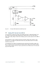
Analog MIC Control Unit (AMCU)
Front panel (see Fig. A.1.3 in Annex 1)
MODE button:
With this button unit chamber voltage U
c
and smoke or density X can be
selected.
CAL button:
When the button is pressed indicator ON light up and the MIC is now ready for
offset calibration by means of the offset trimmer.