


Instruction Manual MIC type EC-912
Revision no.4
11 / 38
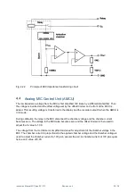
Performance check using an Analog MIC Control Unit (AMCU)
Check the performance of the smoke measuring equipment as follows:
a)
Interconnect the MIC and the Control Cabinet (CC) with the multicable, the MIC
connectors have yellow insulation rings. Align the code marks and push the plug gently into the
connector when fitting the cable.
b)
Connect a voltmeter (range 0-10 VDC) to recorder output X on the rear of the CC.
c)
Connect the CC to the mains and switch on power. The AMCU display shall light up, the MODE
indicator shall indicate Uc mode and the CAL ON indicator shall light up.
d)
Press the AMCU MODE button to indicate mode X. The AMCU display may read a value
deviating from 1.00.
e)
Adjust the offset trimmer on the AMCU until the display reads 1.00. The corresponding recorder
output voltage shall be 10.0 VDC.
f)
Press the AMCU CAL button. The CAL ON indicator shall extinguish. The display may read a
value deviating from 0.00.
g)
Adjust the Uc trimmer on the AMCU until the display reads 0.00. The corresponding recorder
output voltage shall be 0.0 V.
h)
Press the AMCU MODE button to indicate mode Uc. The display shall read a value between
14.0 and 25.0 (19.0 is typical). The voltage on recorder output Uc at the rear of the MCU shall
be the same as the value on the display.
i)
Connect the Vacuum Pump (VP) and air outlet on the rear of the Flow Control Unit (FCU) with a
piece of hose.
j)
Turn the flow meter needle valve in the FCU fully C.W.
k)
Connect the VP to the mains and switch on power. The ball in the flow meter on the FCU shall
stay in its lowest position.
l)
Turn the flow meter needle valve C.C.W. until the middle point of the ball
indicates approx. 30 1/min. Block the air inlet on the rear panel of the FCU with a finger and
control that the ball drops to its lowest position. Fasten the finger screws on the filter unit and
checks for leaks if this does not happen.
Attention:
Do not remove your finger from the air inlet before the VP has been switched off and
stopped. Otherwise, the ball may be damaged by collision with the flow meter needle
valve.
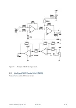
Performance check using an Intelligent MIC Control Unit (IMCU)
Check the performance of the smoke measuring equipment as follows:
a)
Interconnect the MIC and the Control Cabinet (CC) with the multicable, the MIC connectors
have yellow insulation rings. Align the code marks and push the plug gently into the connector
when fitting the cable.