


XenoROL®
22
SWAY BRACING (CEILING HANGER)
1.
Sway bracing should be a minimum of 1-1/2" x
1-1/2" x 3/16" angle.
2.
Sway bracing is secured to the hanger upright
near the conveyor support and extended upward
at an angle of approximately 30 degrees from
the hanger upright. The sway brace angle
should not be over 45 degrees to the upright.
When hangers are installed adjacent to building
columns, a horizontal brace may be installed
securely to the column.
3.
Hanger uprights over 12'-0" in length must have
horizontal bridging angles connected between
the upright and the sway brace at approximately
the half way point.
4.
Sway bracing should be installed on every third
hanger (maximum of 30'-0" centers).
5.
If sway bracing cannot be placed on the outside
of the uprights, alternate X-bracing between
every other pair of uprights.
6.
Additional bracing should be used:
•
Before and after curves
•
At drives
•
At product diverting points
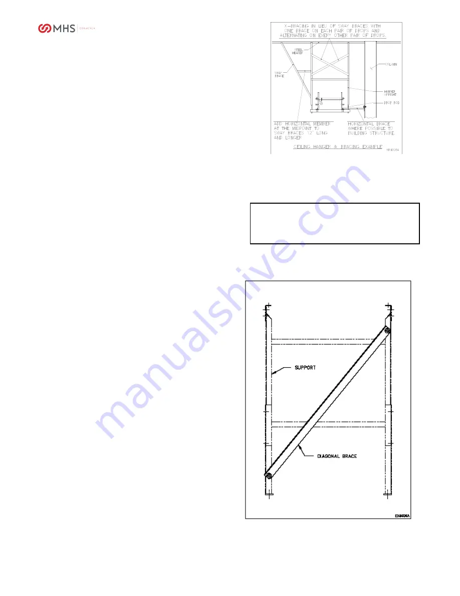
DIAGONAL SWAY BRACE (FLOOR SUPPORT)
Floor support sway bracing
consists of one 1-1/2" x
1-1/2" structural angle and mounting hardware.
APPLICATION: Due to natural side to side
movement of line-shaft conveyor, a diagonal sway
brace has been designed to reduce side movement
in the standard floor support. Side movement is
most prevalent in long straight lines which are not
side braced by adjoining conveyors, curves, etc. or
where they cannot be braced to columns,
machinery, or other conveyors. This is more
noticeable when the conveyor elevation is greater
than its width. One brace can be mounted to every
third or fourth support diagonally across the support
with the low end on the opposite side of every other
brace (alternate orientation). The holes in the
support uprights need to be field drilled.
If excessive oscillation persists after bracing has
been added, it may be the result of harmonics. This
can occur when the conveyor operating speed
generates vibrations with a frequency at or near the
conveyor's natural frequency of its structure. This
rare condition normally occurs between 85 FPM and
120 FPM. It may be minimized by adding more
bracing or by either increasing or decreasing
conveyor speed.
Sometimes it is better not to add a brace at the drive
location. Some experimentation may be required.
CAUTION
Before adding X-braces between uprights,
check for adequate product clearance.
90480006rev092010
Содержание XenoROL XR40
Страница 1: ...XenoROL 1 INSTALLATION OPERATION MAINTENANCE MANUAL XenoROL XR40 and XR48 90480006rev092010...
Страница 9: ...XenoROL 9 90480006rev092010...
Страница 56: ...XenoROL 56 90480006rev092010...
Страница 59: ...XenoROL 59 Input shaft key missing or defective Replace key 90480006rev092010...
Страница 70: ...XenoROL 70 PARTS IDENTIFICATION INTERMEDIATE BEDS CURVES 90480006rev092010...
Страница 71: ...XenoROL 71 PARTS IDENTIFICATION DRIVE PACKAGE AND BED LOW PROFILE DRIVE PACKAGE AND BED 90480006rev092010...
Страница 72: ...XenoROL 72 PARTS IDENTIFICATION URETHANE BELT TRANSFERS URETHANE BELT TRANSFERS OPTIONS 90480006rev092010...
Страница 74: ...XenoROL 74 PARTS IDENTIFICATION WHEEL DIVERTER ASSEMBLY MERGE ASSEMBLY 90480006rev092010...
Страница 75: ...XenoROL 75 PARTS IDENTIFICATION GATE XENOSWITCH ASSEMBLY 90480006rev092010...
Страница 76: ...XenoROL 76 PARTS IDENTIFICATION XENOBRAKE LOCATING STOP AND PIVOTING ROLLER STOP 90480006rev092010...