INSTRUCTION MANUAL
CAUTION: Read All Instructions Before Operating Equipment
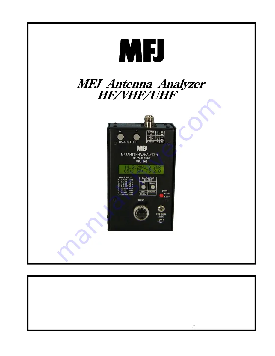
MFJ ENTERPRISES, INC.
300 Industrial Park Road
Starkville, MS 39759 USA
Tel: 662-323-5869 Fax: 662-323-6551
COPYRIGHT 2011 MFJ ENTERPRISES, INC.
C
Model MFJ-266
VERSION 1A
Страница 1: ...AUTION Read All Instructions Before Operating Equipment MFJ ENTERPRISES INC 300 Industrial Park Road Starkville MS 39759 USA Tel 662 323 5869 Fax 662 323 6551 COPYRIGHT 2011 MFJ ENTERPRISES INC C Mode...
Страница 2: ...gulations technical manuals documents positional handbooks or other official publications The copy of this manual provided to the customer will not be updated to reflect current data Customers using t...
Страница 3: ...Local Interference 7 5 2 Checking for Local Interference 7 5 3 Detector Linearity and Accuracy 7 5 4 Calibration Plane Error 8 5 5 Sign Ambiguity 8 6 0 Antenna Measurements 8 6 1 Antenna Connectors 9...
Страница 4: ...anual 2011 MFJ Enterprises Inc iv 7 8 Testing RF Transformers 14 7 9 Checking HF Baluns 15 7 10 Checking Coax Cable 15 8 0 Quick Guide to Analyzer Controls and Functions 16 9 0 Technical Assistance 9...
Страница 5: ...rates a 2 dBm RF signal that may be used to check receivers networks amplifiers and antenna patterns Operating range is HF 1 5 71 MHz in six HF bands VHF 85 185 MHz continuous coverage UHF 300 490 MHz...
Страница 6: ...cted or when the power switch is turned on Doing so could damage the unit Note that alkaline cells are not rechargeable and the analyzer has no built in charging circuitry When replacing old batteries...
Страница 7: ...y to explore the analyzer s basic operating features Begin by pressing the red PWR button on BAND MODE SELECT Up Down ANT Counter Bk Lite PWR ON OFF 3 1 Display Backlight When the analyzer comes on th...
Страница 8: ...Antenna jack the frequency is displayed in MHz Two gate speeds are available The default gate speed is Fast or Fg see the top right hand side of the display The fast gate provides 1 kHz resolution Th...
Страница 9: ...r and will be displayed on the screen see Frequency Selection Section 4 3 6 L C Measurement Mode The MFJ 266 may be used to measure the value of unknown capacitors and inductors To measure L C values...
Страница 10: ...HF VHF and UHF ranges Follow the up down position prompts shown in the table printed next to the buttons to select ranges A B BAND SELECT BAND A B HF X VHF UHF Counter X X means the VHF UHF switch ca...
Страница 11: ...werful enough to overcome any lack of front end selectivity and override stray pickup However a powerful transmitter located nearby could inject enough RF energy into the detector to disrupt readings...
Страница 12: ...nt impact when attempting to measure impedance values because of phase rotation in the cable In fact impedance readings can swing dramatically depending on the cable s electrical length and the severi...
Страница 13: ...impedance is specified by the antenna designer for matching purposes always use 50 Ohm cable of known quality when making up transmission lines and patch cables WARNING Never apply external dc voltag...
Страница 14: ...0 MHz 2 Use the analyzer to measure the present minimum SWR frequency ex 14 050 MHz 3 Divide the present frequency by the desired frequency ex 14 050 14 200 989 4 Multiply the present length by the re...
Страница 15: ...cable is multiple half wavelengths long As a practical matter unless you have an advanced working knowledge of transmission lines Smith charts and impedance matching theory it s best to ignore impeda...
Страница 16: ...ain a peak AC value V rms x 1 414 V p conversely V p x 707 V rms Also despite the display s 0 1 mV resolution readings will be approximations rather than precise values because of detector non lineari...
Страница 17: ...nknown inductor in uH along with the stimulus frequency where the measurement is being made You will not have full control over the stimulus frequency Band selection and the best accuracy is usually o...
Страница 18: ...find the free space 1 4 wavelength in feet L 246 f MHz 6 Divide 9 actual length by free space 1 4 wavelength to get the Velocity Factor VF 9 L Note that there is nothing magical about the 9 foot stub...
Страница 19: ...the input unbalanced side of the balun to the analyzer s antenna connector Connect a center tapped resistive load to the balanced side R1 R2 25 for 1 1 baluns R1 R2 100 for 4 1 baluns Using the Tune a...
Страница 20: ...de Screen Fg f 010 000 MHz REF FS 100mV Set Gate Speed Up Fast Down Slow Incoming Signal Frequency Readout Relative Field Strength Analyzer Mode Screen 50 j 0 50 1 0 Stimulus Frequency Band Frequency...
Страница 21: ...your problem is not solved by reading the manual you may call MFJ Technical Service at 662 323 0549 or the MFJ Factory at 662 323 5869 You will be best helped if you have your unit manual and all inf...
Страница 22: ...MFJ 266 HF VHF UHF Antenna Analyzer Instruction Manual 2011 MFJ Enterprises Inc 18 NOTES...
Страница 23: ...postage and handling 4 This warranty is NOT void for owners who attempt to repair defective units Technical consultation is available by calling 662 323 5869 5 This warranty does not apply to kits sol...
Страница 24: ...MFJ 266 Manual Version 1A Printed In U S A 300 Industrial Park Road Starkville MS 39759...