background image

USE OF SAFETY CHAIN

CAUTION:

A SAFETY CHAIN MUST BE IN-

STALLED TO RETAIN THE CONNECTION BE-
TWEEN TRACTOR (OR OTHER TOWING VEHICLE)
AND SPREADER WHENEVER TRAVELING ON
PUBLIC ROADS IN CASE THE HITCH CONNEC-
TION WOULD SEPARATE. A SUGGESTED AT-
TACHMENT IS ILLUSTRATED ON FIGURE 3.

The chain must be strong enough to hold the weight of
the loaded spreader (See table on page 9). If using a

grab hook at the end(s) of the chain to secure the
chain to itself, a hook latch must be installed.

The length of the safety chain is not to be any longer
than necessary to turn without interference. If any
chain links or attachment hardware are broken or
stretched, repair before using. Store chain so it does
not corrode or become damaged. Do not use this
chain for other implements because the strength and
length of the chain may not be adequate. Identify this
chain for use on this particular spreader. Do not use
the intermediate support as the attaching point.

TRUCK MOUNT SPREADERS

Depending on the make and model of the truck it may
be necessary to install a light converter (MEYER
PART #56-0028). Converter will allow signal lights and
brake lights to operate according to DOT lighting stan-
dard. Call factory for more information.

FREEZING WEATHER OPERATION

Allow spreader to completely empty last of manure
contents and disengage tractor PTO. Shut off tractor,
remove the ignition key and allow all movement to
stop before attempting to clean the spreader.

WARNING

:

DO NOT CLEAN, ADJUST OR

LUBRICATE WHILE SPREADER IS IN MOTION.
FAILURE TO HEED MAY RESULT IN SERIOUS
PERSONAL INJURY OR DEATH.

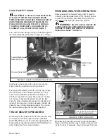
Manually open the trip pan doors at rear of spreader,
figure 4, and scrape clean any remaining manure from
inside the rear of spreader. Clean all manure from rear

Model V-Max

—10—

FIGURE 3. SAFETY CHAIN INSTALLATION

Towing Machine
Attaching Point

Hook w/ hook latch

Safety Chain
Loop.

Intermediate support

FIGURE 4. TRIP PAN DOORS

LOCK HANDLE BEHIND DETENT
TO KEEP DOORS CLOSED

TRIP PAN
DOOR

Содержание V-MAX 2636 Operators

Страница 1: ...Dorchester Wisconsin 54425 Phone 715 654 5132 FAX 715 654 5513 1 800 325 9103 www meyermfg com E mail sales meyermfg com V MAX TWIN EXPELLER SUPER SPREADER MODELS 2636 3245 3954 US PATENT NO 5 368 236 5 501 404 DO NOT OPERATE EQUIPMENT UNTIL THIS MANUAL HAS BEEN READ AND UNDERSTOOD 11 03 ...

Страница 2: ...VE 26 AUGER DRIVE PRIMARY REDUCTION 28 AUGER DRIVE SECONDARY REDUCTION 29 RH AUGER DRIVE FINAL REDUCTION 30 LH AUGER DRIVE FINAL REDUCTION 32 BOX AUGERS SIDE SHAFT 34 UNLOADING GATE TRIP PAN DOORS 36 SPINNERS GEARBOX SHAFT DRIVE 38 SPINNER GEAR REDUCERS 40 HUBS AXLE TANDEM AXLE ASSEMBLY 41 OPTIONAL THIRD AUGER 42 918 0212 PTO DRIVE SHAFT ASSEMBLY 44 918 0312 PTO DRIVE SHAFT ASSEMBLY 44 918 0309 PT...

Страница 3: ...eyer Mfg Corp will repair or replace F O B Dorchester WI as Meyer Mfg Corp elects Ten 10 Years After a period of 1 year the spreader tank body is warranted against rust through for an addi tional period of 9 years Pro Rated Parts Only Parts included front and rear end panels side panels and auger trough IV COMMERCIAL USE Coverage as in paragraph III A1 ONLY except warranty coverage is for 90 days ...

Страница 4: ...t any time without incurring any obligation to owners of units previously sold This supersedes all previous published instructions IMPORTANT At the front of this manual is a Product Registration and Inspection Certificate Be sure your dealer has completed this certificate and promptly forwarded a copy to Meyer Mfg to validate the manufacturer s war ranty The product model and serial number are re ...

Страница 5: ...erating Know how to stop the spreader before starting it Do not operate until all shields covers and guards are in place Make certain everyone is clear of the spreader before applying power Keep hands feet and clothing away from moving parts Loose or floppy clothing should not be worn by the operator Stay well clear of the spreader s rear discharge spinners while operating Do not step up on any pa...

Страница 6: ...indicates an imminently hazardous situation which if not avoided WILL result in death or serious injury WARNING indicates a potentially hazardous situation which if not avoided COULD result in death or serious injury and includes hazards that are ex posed when guards are removed CAUTION indicates a potentially hazardous situation which if not avoided MAY result in minor or moderate injury It is al...

Страница 7: ... OR IF MA NURE SPREADER IS REPAINTED REPLACE DECALS REMEMBER DECALS ARE FOR YOUR PROTECTION AND INFORMATION Decal A 46 3600 9 Decal G 46 0001 26 Decal J 46 3600 1 Decal K 46 3600 8 Decal E 46 0001 4 Decal B 46 0001 5 Decal C 46 0001 22 Decal D 46 0001 13 Decal H 46 3600 6 Decal F 46 0001 35 Decal I 46 0004 2 Decal L 46 3600 2 CAUTION READ ALL DECALS ON THE SPREADER AND IN THIS MANUAL KEEP THESE DE...

Страница 8: ...PERATE WITHOUT ALL SHIELDS GUARDS AND COVERS IN STALLED FAILURE TO HEED MAY RESULT IN SE RIOUS PERSONAL INJURY OR DEATH Fasten the spreader hitch to the tractor drawbar with a hitch pin that cannot bounce out Use 1 diameter hitch pin to pull spreader Remove the weight from the jack jack is not to be used when spreader is loaded Remove jack from square mount tube and move to the transport storage t...

Страница 9: ...errain over which you are traveling Always use caution Avoid traveling on slopes or hills that are unsafe WARNING OBSERVE ALL APPLICABLE TRAFFIC LAWS WHEN TRANSPORTING ON PUBLIC ROADWAYS CHECK LOCAL LAWS FOR ALL HIGH WAY LIGHTING AND MARKING REQUIREMENTS WARNING INSTALL A SMV EMBLEM ON REAR OF SPREADER FOR TRANSPORTING ON ROADWAYS AND KEEP THIS EMBLEM CLEAN AND BRIGHT FAILURE TO HEED MAY RESULT IN...

Страница 10: ...eader Do not use the intermediate support as the attaching point TRUCK MOUNT SPREADERS Depending on the make and model of the truck it may be necessary to install a light converter MEYER PART 56 0028 Converter will allow signal lights and brake lights to operate according to DOT lighting stan dard Call factory for more information FREEZING WEATHER OPERATION Allow spreader to completely empty last ...

Страница 11: ...der to freeze dry Hydrau lically run the flow control rear gate up and down to clean gate slide guides Park spreader with flow con trol rear gate approximately halfway open Before loading in freezing weather manually open and close the trip pan doors at rear of spreader make sure augers and spinners are free to rotate and the flow control rear gate moves freely up and down DANGER KEEP AWAY AND KEE...

Страница 12: ...x while semi liquid and liquid manure will have to be less than full in the spreader box It is unlawful to allow manure to splash or leak onto public roads A liquid manure kit is available for installation around the top of the box on your spreader which will aid in the containment of liquids UNLOADING WARNING MAKE CERTAIN EVERYONE IS CLEAR OF SPREADER BEFORE APPLYING POWER FAILURE TO HEED MAY RES...

Страница 13: ...nd dam age to the chain tighteners NOTE Maximum life of the PTO shaft universal joints will result if you stop the PTO while making turns at the end of the field CAUTION DO NOT EXCEED THE MAXI MUM 80 TURNING ANGLE ON THE CONSTANT VELOCITY PTO DRIVE LINE EXCEEDING THE TURNING ANGLE WILL DAMAGE THE CONSTANT VELOCITY CENTER HOUSING AND WILL EXERT EXCESSIVE PRESSURES ON THE PTO INPUT CENTER SHAFT AND ...

Страница 14: ...AND HYDRAULIC HOSES BEFORE CLEANING ADJUSTING OR SERVICING THIS MACHINE FAILURE TO HEED MAY RESULT IN SERIOUS PERSONAL INJURY OR DEATH Before storing this spreader for an extended period of time perform the following Allow the spreader to completely clean out the last load Thoroughly hose off all manure from the outside of the spreader and the inside of the box particularly getting the flow contro...

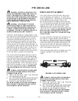
Страница 15: ...ER FORMING THESE STEPS l STOP THE TRACTOR SHUT THE TRACTOR OFF AND REMOVE THE KEY l SET THE PARKING BRAKE AND DISCONNECT THE PTO DRIVE LINE FROM THE TRACTOR l DO NOT ALLOW OTHERS IN THE BOX ROTATING AUGERS CAN CRUSH AND DISMEM BER FAILURE TO HEED MAY RESULT IN SERI OUS PERSONAL INJURY OR DEATH DRIVE LINE ATTACHMENT The cutout clutch end of the PTO drive line must al ways be attached to the impleme...

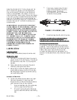
Страница 16: ... should be done with the drive line CV as straight as possible B Slowly articulate the double joint through its maximum joint angle several times C Return the CV joint to its straight position and insert additional grease into the CV Zerk Key 2 until grease is evident around the housing and center sliding disk NORMAL OPERATION A Lubricate the following items after every eight 8 hours of operation ...

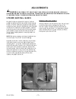
Страница 17: ...spin ner tooth wear bent over or even breakage Adjustments for the 1 8 3 8 clearance of each mate rial guide to spinner tooth is made by tightening or loosening the 1 nut on the material guide spring link age shaft assembly Tighten nut to increase clearance and loosen nut to decrease clearance between the material guides Once recommended clearance is ob tained turn spinners over by hand in the dir...

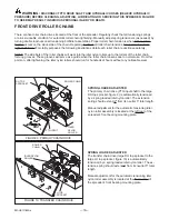
Страница 18: ...ULIC PRESSURE BEFORE CLEANING ADJUSTING LUBRICATING OR SERVICING THIS SPREADER FAILURE TO HEED MAY RESULT IN SERIOUS PERSONAL INJURY OR DEATH FRONT DRIVE ROLLER CHAINS There are five roller chain drives located at the front of the spreader Regularly check that all tensioning springs are in serviceable condition for automatic roller chain tightening Manually adjust spring tensioners as needed by tu...

Страница 19: ...a spring loaded heavy compression spring and tracking yoke idler NYLON roller assembly figure 12 The one heavy compression spring should be compressed to 3 1 2 to 4 in length Manual adjustment for the automatic tensioning idler NYLON roller assembly is located at the left front cor ner of the spreader tank IDLER NYLON ROLLER The side shaft chain drive PTO input shaft to the side line shaft drive s...

Страница 20: ...eader Grease bearings on the RH side line shaft The front bearing is zerk accessible through the RF steel shield ing The remaining rear bearings are located along the RH side of the spreader tank zerks accessible through the steel shielding Grease 4 tandem wing pivots Effectively grease by jacking up the spreader to relieve pressure points on the pivot shaft and tandem wing collar Over greas ing i...

Страница 21: ...kage If leakage is excessive replace required input output shaft seals as needed Lubricate with a Semi Fluid EP Lithium Base Gear Grease Clean and repack the wheel hubs with axle grease an nually Grease hub through zerk in hub monthly Be careful not to over grease and force seal out of back side of hub Model V Max 21 5 ROLLER CHAINS SHIELDS REMOVED ...

Страница 22: ...on of use and regu larly thereafter 2 5 gallon capacity Condensation can occur Drain out water bottom plug as needed l Remove lower plug for draining purposes l Remove reservoir cover or level plug for filling pur pose SEAL COVER TIGHT WITH SILICONE WHEN RE INSTALLING ADJUSTMENTS The 3rd auger drive roller chain large LH top re duction sprocket weldment to the 3rd auger enclosed in the oil bath is...

Страница 23: ...ning the tractors hydraulics only open and close the spreaders rear gate several times This will cycle the hydraulic cylinder leading to the oiler pump Keep cycling until oil can be seen in all of the oil lines leading to the oiler brushes If you experience problems priming the oiler pump you may need to bleed air out of the hydraulic hose where it is connected to the pump Crack the fitting until ...

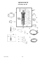
Страница 24: ...Model V Max 24 REPAIR PARTS OPTIONAL OIL KIT 35 ...

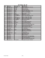
Страница 25: ... 952 0001 1 16 6010 20 Jam Nut 16 952 0001 1 3 4511 Plunger Brass Adj End Cap 17 952 0001 1 32 2107001U 1 8 Hex Head Pipe Plug 18 952 0001 1 18 2550 Reservoir Two Quart Tank 19 952 0001 1 19 M 4555 Hydraulic Hose Assembly Meyer Mfg 20 952 0001 1 20 7010 Tubing 5 8 ID Clear Polybraid 21 952 0001 1 21 7012 Tubing 5 32 Nylon Feet 22 952 0001 1 25 4514 Brush Assembly No 5 32 Insert 23 813 5020 Z 20 Pl...

Страница 26: ...Model V Max 26 FRONT SHIELD SIDE SHAFT DRIVE ...

Страница 27: ...chine Bushing As Required 13 910 0015 80B18 Sprocket 1 1 2 Bore 3 8 Keyway 14 808 1 5 2 25 10 10 Ga Machine Bushing As Required 15 813 3118 Z 5 16 16 Nut Zinc 16 808 1 1 5 18 18 Ga Machine Bushing As Required 17 933 3804 5 16 18 x 4 Eye Bolt Fully Threaded 18 925 3822 6 2 Link 3 16 Proof Coil Chain Prior To SN SV063245240 19 929 0003 Tightener Spring 20 38 0013 5 16 x 1 3 4 Roll Pin 21 955 3703 Ga...

Страница 28: ... Keyway 7 RPM on Au gers 910 0005 Sprocket 80B12 1 1 2 Bore 3 8 Keyway 5 RPM on Au gers KEY PART NO DESCRIPTION 9 914 3602 Bearing 4 Bolt Flange 1 1 2 Bore 10 925 3606 Front Bearing Plate Bent 11 925 3883 Tightener Assembly Complete 12 931 3810 CV OR PTO Shied Assembly 13 923 3833 CV OR Input Drive Shaft Splined 923 3833 XL CV OR Input Drive Shaft Opt 19 Ext Hitch 14 910 0063 Welded Sprocket Assy ...

Страница 29: ... Nylon Roller Only 6B 912 0013 2 Inner sleeve 7 808 75 1 25 14 Machine Bushing 14GA 8 925 3884 1 Second Reduction Tightener Arm Weldment 9 813 3118 Z 5 16 Regular Nut 10 933 3804 5 16 x4 Full Thread Eye Bolt 11 925 3822 6 2 Links 3 16 Proof Coil Chain Prior To SN SV063245240 12 929 0003 Spring 13 808 1 1 5 18 Machine Bushing 18GA 14 910 0064 Welded Sprocket Assy LH 80 60 x 120 9 15 925 3884 Tighte...

Страница 30: ...Model V Max 30 RH AUGER DRIVE FINAL REDUCTION Install 120 56 Roller Chain Key 13 W Connector Link Cotter Pins Facing Towards Front Of Spreader ...

Страница 31: ...t 6 913 3801 1 Auger Bushing Only 2 1 2 ID x 2 3 4 OD x 2 3 4 Long 7 925 3834 Front Auger Bearing Plate Assm With Bushing RH 8 933 3621 3 4 Jam Nut 9 808 75 1 25 14 Machine Bushing 14GA 10 912 0013 Tightener Roller 2 Nylon Complete 10A 912 0013 1 Nylon Roller Only 10B 912 0013 2 Inner Sleeve 11 925 3848 7 Tightener Arm Welded Assy 12 929 3601 Spring 13 911 0023 Chain 120x56 pitches 14 851 7510 3 5...

Страница 32: ...Model V Max 32 LH AUGER DRIVE FINAL REDUCTION Install 120 72 Roller Chain Key 21 W Connector Link Cotter Pins Facing Towards Rear Of Spreader ...

Страница 33: ...ylon Complete 20A 912 0014 1 Nylon Roller Only 20B 912 0014 2 Inner Sleeve 21 911 0024 Chain 120x72 pitches 21A 911 0026 120 Connector Link Only 22 912 0001 Nylon Roller 23 925 3838 Tightener Weldment Yoke 24 925 3842 Outer Slide Nut Assembly 25 910 0028 Auger Sprocket 120B33 Splined 910 0101 Shear Sprocket Assy 120B33 831 5020 1 75 20 x 1 3 4 Allen Head Cap Screw Grade 8 884 5020 20 Top Locknut G...

Страница 34: ...Model V Max 34 BOX AUGERS SIDE SHAFT ...

Страница 35: ...sset No Ext 15 901 3816 27 Poly Board Top Rail 2636 901 3816 28 Poly Board Top Rail 3245 901 3816 29 Poly Board Top Rail 3954 16 901 3830 5 Rear Splash Guard KEY PART NO DESCRIPTION 17 851 5013 1 25Z 13x1 1 4 Bolt GR5 18 810 5013 Z Flange Lock Nut 19 901 3816 30 Extension Back Rail 20 901 3830 5 Front Splash Guard No Ext 901 3830 8 Front 45 Splash Guard w Ext 21 914 3801 Pillow Block Bearing 1 3 8...

Страница 36: ...Model V Max 36 UNLOADING GATE TRIP PAN DOORS Prior to 08 Serial Nos ...

Страница 37: ...3 Gate Pivot Shaft Sleeve 29 901 3838 2 Gate Pivot Arm Shaft 30 901 3846 Back Gate Holder Hook 31 925 3852 Corner Gearbox Mounting Plate 32 901 3853 Corner Gearbox Support Gusset 33 901 3844 1 Gearbox Mounting Channel 34 925 3857 Rear Lower Skid Plate 35 955 3802 10 Cylinder Pivot Pin W Clips 36 822 0050 Z Split Lock Washer 37 29 0009 Adjustment Spring 38 925 3768 2 Spring Pivot Pin Assembly 39 92...

Страница 38: ...Model V Max 38 SPINNERS GEARBOX SHAFT DRIVE PRIOR TO 08 SERIAL NOS ...

Страница 39: ...ial s 924 5011 Rear Shield Assembly 08 Serial s Later 13 924 3818 RR Shield Assembly 14 937 0009 2 Coupler Chain 937 0009 3 Connecting Link 15 808 1 38 2 5 14 Machine Bushing 14GA 808 1 38 2 5 18 Machine Bushing 18GA 808 1 38 2 5 10 Machine Bushing 10GA 16 901 3855 4 Splined Hub 17 851 5013 1 25Z 13 x 1 1 4 Bolt GR5 18 815 5013Z 13 Nylon Insert Lock Nut 19 921 0001 1 3 8 One Piece Set Collar 20 32...

Страница 40: ...10 19 0043 1 Corner Gearbox Casting tapped holes Cast 11 19 0042 1 Center Gearbox Casting tapped holes Cast 12 19 0041 1 LH Gearbox Casting tapped holes Cast 13 19 0041 2 RH LH Center Gearbox Casting thru holes Cast 14 19 0024 20 Bolt 1 SHCS 16 19 0016 5 Plug NPT Plain 17 19 0023 1 PF RH Gearbox Pinion Output Shaft Gear Assy 18 19 0023 2 3 8 Drilled Fill Plug Bolt 19 55 0107 Breather Plug 20 19 00...

Страница 41: ...s Complete 901 3861 NA Tandem Beam w Spindles Only Prior to Serial SV083954527 901 3891 NA Tandem Beam w Hubs Complete Prior to Serial SV083954527 901 3861 R NA Right Beam Offset Pivot Less Hubs Serial SV083954527 Later 901 3861 L NA Left Beam Offset Pivot Less Hubs Serial SV083954527 Later KEY PART NO M 3954 PART NO M 2636 3245 DESCRIPTION 20 901 3898 NA Right Beam Offset Pivot W Hubs Serial SV08...

Страница 42: ...Model V Max 42 OPTIONAL THIRD AUGER Items 10 and 11 are used on two auger units only ...

Страница 43: ...13 3805 Bronze Bushing 14 925 3865 3rd Auger Rear Shaft Support Sleeve w Bushing 15 933 3630 Copper Tube Grease Line 13 includes zerk fittings 16 926 3819 Third Auger Assembly 2636 926 3820 Third Auger Assembly 3245 926 3821 Third Auger Assembly 3954 17 933 3804 Eyebolt Full Thread 18 925 3825 Tightener Angle Clip 19 813 3118 Z 5 16 18 Nut Zinc 20 851 6311 2Z 5 8 11x2 Gr 5 Machine Bolt 21 814 6311...

Страница 44: ...r to Serial SV083954451 918 0312 1 1 Cut Out Clutch 1900NM Se rial SV083954451 Later 12 918 0208 2 4 Bearing Ring SC25 13 918 0208 2 5 Outer Shield Tube OVL 14 918 0208 1 7 Inner shield Tube Round 15 918 0208 1 8 CV Cone Bearing Assy 16 918 0208 1 9 Shield Cone 3 Rib KEY MEYER PART NO DESCRIPTION 17 918 0208 2 6 Shield Cone 8 Rib 18 918 0208 2 7 Safety Chain 19 918 0208 2 8 Decal Out In Item 13 20...

Страница 45: ...m 2 NS 918 0208 2 3 11 Shim Kit PRIOR TO SERIAL SV083954451 540 RPM 1 3 8 6 SPLINE YOKE WWE2480 80 DEGREE C V SERIAL SV083954451 LATER 540 RPM 1 3 8 6 SPLINE YOKE WWE2480 80 DEGREE C V KEY MEYER PART NO DESCRIPTION 1 918 0308 2 2 1 Housing 2 918 0308 2 2 2 Hub 3 918 0312 1 1 1 Spring Pack 1900NM 4 918 0208 2 3 5 Washer 5 918 0208 2 3 6 Retaining Ring 6 918 0208 2 3 7 Sealing Ring 7 918 0208 2 3 1 ...

Страница 46: ...5 13 918 0309 2 3 Outer Shield Tube OVL 4 Shorter 14 918 0309 1 1 Inner shield Tube Round 4 Shorter 15 918 0308 1 3 CV Cone Bearing Assy 16 918 0308 1 4 Shield Cone 3 Rib 17 918 0308 2 5 Shield Cone 8 Rib 18 918 0208 2 7 Safety Chain KEY MEYER PART NO DESCRIPTION 19 918 0208 2 8 Decal Out In Item 13 20 918 0208 1 10 Decal In In Item 8 21 918 0208 2 9 Screw In Item 15 16 17 22 918 0208 1 11 Support...

Страница 47: ...taining Ring 6 918 0208 2 3 7 Sealing Ring 7 918 0208 2 3 1 Clamp Cone Assembly 8 918 0208 2 3 8 Cam NS 918 0208 2 3 9 Bushing In Item 2 NS 918 0208 2 3 11 Cutout Clutch Shim Kit See page 46 for PTO Drive Shaft Assembly 918 0309 PTO DRIVE SHAFT ASSEMBLY 1000 RPM 1 3 8 21 SPLINE SP STANDARD 918 0311 PTO Drive Shaft Assembly 1000 RPM 1 3 4 20 SPLINE OPTIONAL CUTOUT CLUTCH ...

Страница 48: ...11 11 918 0208 2 3 Cut Out Clutch 2100NM 12 918 0208 2 4 Bearing Ring SC25 13 918 0209 2 1 Outer Shield Tube OVL 4 Shorter KEY MEYER PART NO DESCRIPTION 14 918 0209 1 1 Inner shield Tube Round 4 Shorter 15 918 0208 1 8 CV Cone Bearing Assy 16 918 0208 1 9 Shield Cone 3 Rib 17 918 0208 2 6 Shield Cone 8 Rib 18 918 0208 2 7 Safety Chain 19 918 0208 2 8 Decal Out In Item 13 20 918 0208 1 10 Decal In ...

Страница 49: ... 918 0208 2 3 6 Retaining Ring 6 918 0208 2 3 7 Sealing Ring 7 918 0208 2 3 1 Clamp Cone Assembly 8 918 0208 2 3 8 Cam NS 918 0208 2 3 9 Bushing In Item 2 NS 918 0208 2 3 11 Shim Kit PRIOR TO 08 SERIAL NOS 918 0209 PTO DRIVE SHAFT ASSEMBLY 1000 RPM 1 3 8 21 SPLINE STANDARD 918 0211 PTO DRIVE SHAFT 1000 RPM 1 3 4 20 SPLINE OPTIONAL WWE2480 80 DEGREE C V ...

Страница 50: ...14 3809 Output Quill Bearing 2 14 914 3816 Input Shaft Bearing 2 15 914 3817 Input Shaft Bearing Race 2 16 923 3834 Splined Input Shaft 1 17 923 3835 Output Quill 1 18 925 3890 1 Chain Tightener Weldment Less Roller 1 19 925 3891 1 Front Cover Plate Welded Assembly 1 20 925 3892 10 2 1 8 Seal 1 21 925 3892 1 Main Tube Weldment 1 22 925 3892 9 1 1 2 Seal 1 23 933 3812 Input Shaft Spacer 1 24 955 38...

Страница 51: ... TR Truck Mount Dual Light RH w 4 Plug Serial SV063245328 Later 1 KEY PART NO DESCRIPTION QTY 3 56 0003 Ag Light Harness W Bullet Terminals Prior to Serial SV063245328 1 56 0032 Ag Light Harness W Mod ule Serial SV063245328 Later 1 4 56 0004 1232 4 Way Socket 4 Pin 1 5 56 0005 Coil Cable Assy 1 5a 56 0012 7 Contact Plug Only 1 5b 56 0005 1 4 Hole Plug End Only 1 6 56 0008 Harness Frame Clip 3 7 56...

Страница 52: ...s Replace slide guide poly slick GEAR BOXES Clunking sounds Excessive oil use Gear damage Gears bearings wearing low level of liquid grease Worn out oil seals Dry manure twine wrapping High speed full load start up Worn out gears Replace gears bearings fill with semi fluid EP lithium base gear grease Replace oil seals Clean remove build up at seal areas Slow start up fill with oil Replace gears MA...

Страница 53: ...ion Excessive paddle damage Bad lower spinner bearings Spinner bent out of bal ance Worn out lower spinner sleeve shaft Too slow spinner RPM s Lodging of manure Spreading foreign objects Replace lower spinner bearings Straighten balance replace spinner Replace lower spinner sleeve shaft and reweld Operate spreader at rec ommended 540 RPM Adjust material guides Straighten replace pad dles Keep shar...

Страница 54: ...Model V Max 54 MEYER SUPER SPREADER MAINTENANCE RECORD Model No ____________________Serial No ____________________ Delivery Date ____________________ DATE SERVICE PERFORMED DATE SERVICE PERFORMED ...

Страница 55: ...g Bolt 85 ft lbs 9 16 7 8 80 ft lbs Lug Bolt 120 ft lbs 5 8 15 16 1 1 16 100 ft lbs Bevel or Flange Nut 160 ft lbs 3 4 1 1 8 1 1 2 Flange Nut 378 ft lbs TIRE INFLATION TIRE SIZE PLY PSI 11L 15 8 36 12 5L 15 8 36 12 5L 15 12 52 14L 16 12 44 16 5L 16 10 36 19LX16 1 10 32 21 5L 16 1 18 44 11R 22 5 used truck 75 425 65X22 5 used truck 75 28L 26 16 28 ...

Страница 56: ...ngle 96 tandem 96 tandem Tank Steel copper bearing 3 16 3 16 3 16 Frame construction channel 8 8 8 Spindle Size 2 3 4 2 3 4 3 Hub Size 8 Bolt 6 000 lbs 8 Bolt 6 000 lbs 8 Bolt 8 000 lbs Expellor Size 20 20 20 Expellor Speed 540 RPM 540 RPM 540 RPM Auger Speed 10 RPM 10 RPM 10 RPM Tractor PTO Speed Max 540 or 1000 RPM optional 540 or 1000 RPM optional 540 or 1000 RPM optional Auger Diameter 20 20 2...

Страница 57: ...Model V Max 57 ...

Страница 58: ...Model V Max 58 ...

Страница 59: ...Model V Max 59 ...

Страница 60: ...E ...

Отзывы: