IMO-553
EN •
11
/201
9
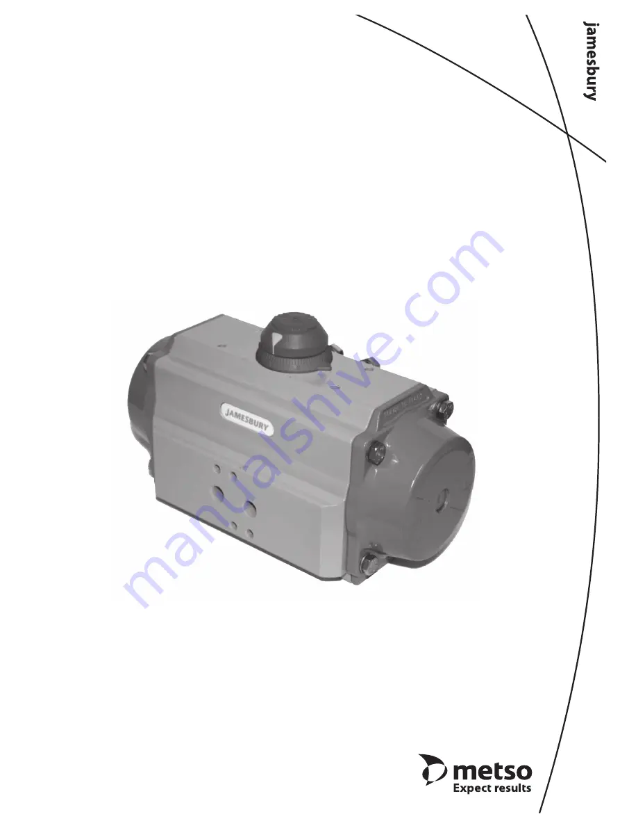
Valv-Powr® VPVL
Mod D Value-Line®
Double-Opposed Piston Actuators
Installation, Maintenance and
Operating Instructions
Страница 1: ...IMO 553 EN 11 2019 Valv Powr VPVL Mod D Value Line Double Opposed Piston Actuators Installation Maintenance and Operating Instructions ...
Страница 2: ... the latest documentation SAVE THESE INSTRUCTIONS Subject to change without notice All trademarks are property of their respective owners TABLE OF CONTENTS 1 GENERAL 3 1 1 Warning 3 1 2 Handling VPVL Actuators 3 2 TECHNICAL DATA 3 3 INSTALLATION 4 3 1 General 4 3 2 Operation 4 4 MAINTENANCE 4 4 1 General 4 4 2 Disassembly 4 4 3 Assembly 7 5 SAFETY LOCKOUT DEVICE 10 6 Declutchable Manual Override D...
Страница 3: ... THE VALVE AND ACTUATOR BE SURE THAT THE INDICATOR POINTER ON TOP OF THE ACTUATOR AND THE IDENTIFICATION PLATE IN FEMALE ACTUATORS ARE CORRECTLY INDICATING THE VALVE POSITION FAILURE TO ASSEMBLE THESE PRODUCTS TO INDICATE CORRECT VALVE POSITION COULD RESULT IN DAMAGE OR PERSONAL INJURY THE ACTUATOR MUST BE SIZED ACCURATELY FOR PROPER OPERATION REFER TO INFORMATION ON THE ACTUATOR END OF STROKE TOR...
Страница 4: ... Section 4 3 5 3 2 Operation 1 The actuator series size operating pressure operating temperature output torque spring directions and drive type is determined by the actuator designation 2 The label lists the actuator series size operating pressure maximum pressure and serial number 3 Actuator designation example VPVL300SR6BD is a spring return series VPVL300 double opposed piston actuator that has...
Страница 5: ...nd cap bolts 13 in the sequence shown in Figure 5 CAUTION VPVL051 Thespringswithinthespringreturn version of the size 051 actuator are not captured in a cartridge The end cap bolts are 30mm long to allow the spring force to be completely released prior to removal of the end caps 30 Slowly back out all 4 end cap screws 13 evenly to allow the spring force to be safely released prior to removal of th...
Страница 6: ...ply downward force to top of drive shaft 60 until it is partially out of the bottom of the body 50 and the octi cam 1 and internal thrust bearing 8 can be removed Remove the octi cam 1 and internal thrust bearing 8 Push the drive shaft 60 completely out of the bottom of the body 50 If the shaft 60 does not move freely gently tap with a plastic mallet C Remove the top and bottom shaft bearings 6 7 ...
Страница 7: ...16 and the piston head 15 and piston back 5 bearings B Apply grease to the internal bore of the body 50 using a recommended o ring area grease listed in Table 2 Apply grease to the piston 40 rack teeth using a recommended general purpose grease listed in Table 2 60 50 Figure 10 C Hold the body 50 in a horizontal position by inserting the top of the shaft in a vice or inserting the bottom of the sh...
Страница 8: ...d the 90 vertical centerline of the actuator body 50 and a minimum of 5 beyond the 0 horizontal centerline of the actuator body as shown in Figure 13 If the proper stroke is not obtained remove the pistons and repeat from step 2d Once the proper stroke is verified remove the position indicator 19 5 Figure 13 3 End Cap 30 and Spring Cartridge 17 Assembly Figures 14 through 16 A For spring return ac...
Страница 9: ...ure to determine if the valve is in the proper position In most applications this will be fully opened E If the valve is not in the correct counter clockwise position turn the left stop adjustment screw 2 IN to reduce actuator travel or OUT to increase actuator travel F When the correct counter clockwise position is obtained hold the adjusting screw 2 stationary while tightening the lock nut 4 6 P...
Страница 10: ...f one travel stop screw leaving it partially threaded in the end cap Entirely remove the other stop screw from the other end cap B Open valve using air pressure Note actuator will leak due to removed travel stop C Keeping air pressure applied to actuator use the indicator pointer on top of actuator to determine if valve is open to desired position If not remove air pressure and repeat steps 1 3 ba...
Страница 11: ...Actuator Body until the desired lock position is achieved then tighten the Special Nut 228 see Figure 21 WARNING THE LOCK OUT FEATURE CAN BE RENDERED INEFFECTIVE BY A MIS ALIGNED OCTI CAM SEE FIGURE 11 WHICH COULD CAUSE DAMAGE TO EQUIPMENT OR PERSONAL INJURY FUNCTIONAL TESTING IS RECOMMENDED ON INITIAL INSTALLATION OF LOCKING DEVICES AND AFTER ANY SERVICE OR REPAIR TO CONFIRM THE EFFECTIVENESS OF ...
Страница 12: ...ion cannot be achieved loosen the stop screw close on the gearbox Figure 23 and check the travel stop adjustment of the actuator Once fully open is achieved hand tighten the stop screw and secure with the lock nut 4 Turn the handwheel counter clockwise to put the gearbox valve in the fully opened position When the fully open position cannot be achieved loosen the stop screw open on the gearbox Fig...
Страница 13: ...ir supplyports 8 SERVICE SPARE PARTS We recommend that actuators be directed to our service centers for maintenance The service centers are equipped to provide rapid turn around at a reasonable cost and offer new actuator warranty with all reconditioned actuators NOTE When sending goods to the service center for repair do not disassemble them Clean the actuator prior to shipping For further inform...
Страница 14: ...on Special NBR 17 min 5 max 12 Spring Cartridge Alloy Steel Epoxy Coated 18 1 Spring Clip Pinion Spring Steel ENP 19 0 1 Graduated Ring High Grade Polymer 19 1 1 Position Indicator High Grade Polymer 19 5 1 Top Adaptor Extruded Aluminum Anodized 19 6 2 Hex Socket Set Screw Stainless Steel 20 xy 1 O ring Pinion Bottom Special NBR 21 xy 1 O ring Pinion Top Special NBR 30 2 End Cap Cast Aluminum Anod...
Страница 15: ...4 53 5 6 VPVL100 M6 10 89 97 10 11 VPVL200 M6 10 89 97 10 11 VPVL250 M6 10 89 97 10 11 VPVL300 M8 13 17 18 23 24 VPVL350 M8 13 17 18 23 24 VPVL400 M10 17 35 38 47 52 VPVL450 M10 17 35 38 47 52 VPVL500 M12 19 60 63 81 85 VPVL550 M12 19 60 63 81 85 VPVL600 M14 22 97 102 132 138 VPVL650 M16 24 148 155 201 210 VPVL700 M14 22 97 102 132 138 ...
Страница 16: ... the intended service contact Metso for more infromation HOW TO ORDER To specify a complete Valv Powr Value Line Actuator simply make a selection from the code boxes below EXAMPLE VPVL 400 SR4 5 B AS D shown below is a 59 FT LBS 60 psi 84 N m 4 2 bar spring return actuator with spring to close rotation hard anodized PTFE coated body polyester coated end caps standard temperature rating and 100 adj...