Electrical Installation Safety Trainer
AD 1 - MI 3399
95
2
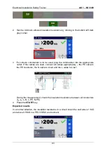
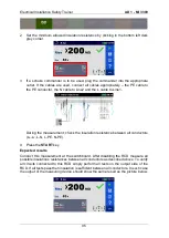
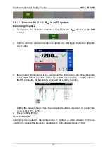
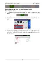
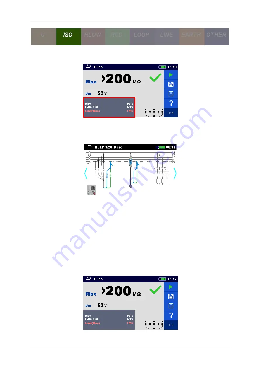
Set the minimum allowed insulation resistance by clicking in the bottom left dark
grey corner.
3
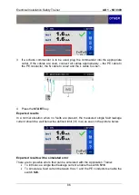
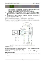
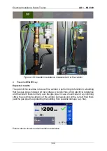
If a schuko commander is to be used, plug the commander into the appropriate
outlet. If the cables are used, connect all cables appropriately
– the PE cable to
the PE conductor, the N cable to Line2 and the L cable to Line1.
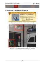
During the measurement, check the insulation resistance between all conductors
(L
X
-L
Y
, L-N, L-PE. N-PE).
4
Press the
START
key.
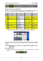
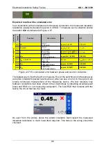
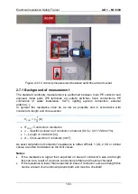
Expected results
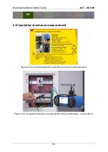
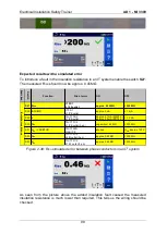
Conduct this measurement at the switchboard. After disabling the RCD measure all
possible insulations resistances between all conductors as described above. To verify
all circuits connected to this RCD simply perform all tests on the output side of the
RCD. If all tests pass then insulation is sufficient between all conductors. In such case
the output of the measuring device should show the same result as the picture below.
Содержание MI 3399
Страница 27: ...Electrical Installation Safety Trainer AD 1 MI 3399 27...
Страница 28: ...Electrical Installation Safety Trainer AD 1 MI 3399 28 AD 1 MI 3399 EIS Electrical Installation Safety Trainer...
Страница 46: ...Electrical Installation Safety Trainer AD 1 MI 3399 46 3 Exit settings...
Страница 74: ...Electrical Installation Safety Trainer AD 1 MI 3399 74...
Страница 122: ...Power and Voltage Quality Trainer AD 2 MI 3399 122 AD 2 MI 3399 PQA Power and Voltage Quality Trainer...
Страница 197: ...Power and Voltage Quality Trainer AD 2 MI 3399 197 Figure 4 89 Transient Chart view...
Страница 204: ...PAT Appliances Machines Safety Trainer AD 3 MI 3399 204...
Страница 205: ...PAT Appliances Machines Safety Trainer AD 3 MI 3399 205 AD 3 MI 3399 PAT Appliances Machines Safety Trainer...
Страница 249: ...PV Photovoltaic Systems Trainer AD 4 MI 3399 249...
Страница 250: ...PV Photovoltaic Systems Trainer AD 4 MI 3399 250 AD 4 MI 3399 PV Photovoltaic Systems Trainer...

