


29
13.8
Connection of temperature sensors
Sensor wires may be extended using wires of
cross-section area not less than 0.5 mm
2
.
Total length of wires of each sensor should
not exceed 15 m.
Insert boiler temperature sensor into
thermometer well fastened to boiler shell.
Fasten feeder temperature sensor to the
surface of feeder screw tube. Insert
temperature sensor of HUW container into
thermometer well welded to the container.
The best way to mount mixer temperature
sensor is to insert it into a sleeve located in
the stream of flowing water, however, it is
also allowed to fasten the sensor in a contact
manner provided that the sensor and the
pipe are properly heat-insulated.
Sensors shall be protected against
loosening from surfaces they are
mounted to.
Make sure thermal contact between the
sensors and the surface which temperature is
measured is good. Apply thermal paste to
improve the contact. Pouring sensors with oil
or water is not allowed. Sensor wires should
be separated from power supply wires.
Otherwise, temperature indications may be
erroneous. Min. distance between these
wires should be 10 cm.
Do not allow sensor wires to contact hot
parts of the boiler and heating system. Wires
of temperature sensors are heat resistant to
the temperature not exceeding 100°C.
13.9
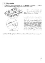
Connecting weather sensor
The regulator cooperates only with a weather
sensor of the CT6-P type. The sensor should
be installed on the coldest wall of the
building, usually this is the northern wall,
under a roof. The sensor should not be
exposed to direct sunlight and rain. The
sensor should be fitted at least 2 m above
the ground, far from windows, chimneys and
other heat sources which could disturb the
temperature measurement (at least 1,5 m).
Connect the sensor using cable of 0,5 mm
2
cross-section, up to 25 m long. Polarity of
the leads is insignificant. Connect the other
end of the cable to the regulator.
Attach the sensor to the wall using tackbolts.
To access the tackbolts holes, unscrew the
sensor lid.
13.10
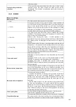
Checking temperature sensors
The temperature sensor can be checked by
measuring its resistance in a given
temperature. Replace the sensor if there are
significant differences between the measured
resistance and the values provided in the
table below.
CT4
Ambient temp.
°C
Min.
Ω
Rated
Ω
Max.
Ω
0
802
815
828
10
874
886
898
20
950
961
972
25
990
1000
1010
30
1029
1040
1051
40
1108
1122
1136
50
1192
1209
1225
60
1278
1299
1319
70
1369
1392
1416
80
1462
1490
1518
90
1559
1591
1623
100
1659
1696
1733
exhaust CT2S-2, CT6-P
Temp.
°C
Min.
Ω
Rated
Ω
Max.
Ω
0
999.7
1000.0
1000.3
25
1096.9
1097.3
1097.7
50
1193.4
1194.0
1194.6
100
1384.2
1385.0
1385.8
125
1478.5
1479.4
1480.3
150
1572.0
1573.1
1574.2
Содержание ecoMAX860P2-T
Страница 2: ...2...
Страница 6: ......
Страница 7: ...REGULATOR INSTRUCTION MANUAL ecoMAX860P2 T...
Страница 19: ...19 CONTROLLER INSTALLATION AND SERVICE SETTINGS MANUAL ecoMAX860P2 T...
Страница 43: ......
Страница 44: ......
Страница 45: ......
Страница 46: ......
Страница 47: ......
Страница 48: ...Jacek Kucharewicz ul Sikorskiego 66 16 100 Sok ka Poland tel 48 85 711 94 54 www metalfachtg com pl...


