background image

NOTICE

Operating  the  engine  with  the  outboard  in  the  tilt  range  can  damage  the

engine  or  the  transom.  If  operating  the  engine  in  the  tilt  range,  such  as  in

shallow water, do not exceed 2000 RPM.

1. Reduce the engine speed below 2000 RPM.
2. Tilt the outboard up. Make sure all the cooling water intake holes stay

submerged at all times.

3. Operate the engine at slow speed only.

The outboard will remain at the selected tilt position, however, the engine RPM

will be limited.

Propeller Steering Torque—Trim Tab Adjustment

Propeller steering torque may cause your boat to pull in one direction. Steering

torque normally occurs at or above planing speeds. Higher speed causes

higher steering torque loads. The trim tab can compensate for normal steering

torque in many cases and can be adjusted within limits to reduce any unequal

steering effort.

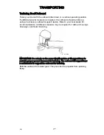
26816

NOTE: Trim tab adjustment will have little effect reducing steering torque if the

outboard is installed with the antiventilation plate approximately 50 mm (2 in.)

or more above the boat bottom.
TRIM TAB ADJUSTMENT

Operate your boat at normal cruising speed and trim position. Turn the boat left

and right and note the direction the boat turns more easily.
If adjustment is necessary, loosen the trim tab fastener and make small

adjustments at a time. If the boat turns more easily to the left, move the trailing

edge of the trim tab to the left. If the boat turns more easily to the right, move

the trailing edge of the trim tab to the right. Tighten the fastener and test.

FEATURES AND CONTROLS

eng

35


Содержание Optimax 150

Страница 1: ...Operation Maintenance and Installation Manual 2017 Mercury Marine 150 150 SeaPro FourStroke 8M0133564 517 eng ...

Страница 2: ...eng ...

Страница 3: ...anual Thoroughly IMPORTANT If you do not understand any portion of this manual contact your dealer Your dealer can also provide a demonstration of actual starting and operating procedures Notice Throughout this publication and on your power package warnings cautions and notices accompanied by the International Hazard Symbol may be used to alert the installer and user to special instructions concer...

Страница 4: ...ased on continuous improvement reserves the right to discontinue models at any time or to change specifications or designs without notice and without incurring obligation Warranty Message The product you have purchased comes with a limited warranty from Mercury Marine the terms of the warranty are set forth in the Warranty Manual included with the product The Warranty Manual contains a description...

Страница 5: ...Skyhook SmartCraft Sport Jet Verado VesselView Zero Effort Zeus 1 On the Water and We re Driven to Win are registered trademarks of Brunswick Corporation Pro XS is a trademark of Brunswick Corporation Mercury Product Protection is a registered service mark of Brunswick Corporation Identification Records Please record the following applicable information Outboard Engine Model and Horsepower Engine ...

Страница 6: ...eng iv ...

Страница 7: ...10 Exhaust Emissions 12 Selecting Accessories for Your Outboard 14 Safe Boating Recommendations 14 Recording Serial Number 17 Specifications 150 17 Specifications 150 SeaPro 18 Component Identification 20 Transporting Trailering Boat Outboard 21 Fuel and Oil Fuel Requirements 22 Fuel Additives 23 Low Permeation Fuel Hose Requirement 23 Quick Disconnect Fuel Hose Fitting 23 EPA Pressurized Portable...

Страница 8: ...Water 38 Engine Break in Procedure 39 Starting the Engine 39 Gear Shifting 42 Stopping the Engine 42 Maintenance Cleaning Care Recommendations 43 EPA Emissions Regulations 45 Inspection and Maintenance Schedule 46 Maintenance Schedule Decal 150 FourStroke 48 Flushing the Cooling System 49 Top Cowl Removal and Installation 50 Battery Inspection 51 Fuel System 51 Corrosion Control Anode 53 Propeller...

Страница 9: ...Ordering Literature 76 Outboard Installation Mercury Marine Validated Engine Mounting Hardware 78 Accessories Mounted to the Transom Clamp Bracket 78 Important Information 82 Boat Horsepower Capacity 82 Start in Gear Protection 83 Fuel System 83 Installation Specifications 88 Lifting Outboard 88 Shipping Bracket Removal 89 Steering Cable Starboard Side Routed Cable 90 Steering Link Rod Fasteners i...

Страница 10: ...Maintenance Log Maintenance Log 112 viii eng ...

Страница 11: ...ng with using good common sense can help prevent personal injury and product damage This manual as well as safety labels posted on the outboard use the following safety alerts to draw your attention to special safety instructions that should be followed WARNING Indicates a hazardous situation which if not avoided could result in death or serious injury CAUTION Indicates a hazardous situation which...

Страница 12: ...ts in the propulsion system An improper propeller choice can significantly affect the performance of your boat and could result in damage to the outboard engine When choosing a propeller a full selection of aluminum and stainless steel propellers specifically designed for your outboard are available through Mercury Marine To view the entire product offering and find the correct propeller that is b...

Страница 13: ...ign of your outboard However when more than one diameter is available for the same pitch use a larger diameter for heavy boat applications and a smaller diameter for lighter applications Pitch The pitch is the theoretical distance in inches that a propeller travels forward during one revolution Pitch can be thought of similar to gears in a car The lower the gear the faster the car will accelerate ...

Страница 14: ...y of sizes and styles that allow you to dial in the ultimate performance for your boat 3 BLADE VS 4 BLADE Available in many sizes of both aluminum and stainless 3 and 4 blade propellers have unique performance characteristics In general 3 blade propellers offer good all around performance and higher top speed than 4 blade propellers However 4 blade propellers are usually faster to plane and more e...

Страница 15: ... thrown within or out of the boat Always use required components and follow instructions and torque procedures a Self locking nuts Lanyard Stop Switch The purpose of a lanyard stop switch is to turn off the engine when the operator moves far enough away from the operator s position as in accidental ejection from the operator s position to activate the switch Tiller handle outboards and some remote...

Страница 16: ...rd stop switch is to stop the engine when the operator moves far enough away from the operator s position to activate the switch This would occur if the operator accidentally falls overboard or moves within the boat a sufficient distance from the operator s position Falling overboard and accidental ejections are more likely to occur in certain types of boats such as low sided inflatables bass boat...

Страница 17: ... the operator s station without first disconnecting the stop switch lanyard from the operator Accidental or unintended activation of the switch during normal operation is also a possibility This could cause any or all of the following potentially hazardous situations Occupants could be thrown forward due to unexpected loss of forward motion a particular concern for passengers in the front of the b...

Страница 18: ... Stop the engine immediately whenever anyone in the water is near your boat Shift the outboard into neutral and shut off the engine before allowing people to swim or be in the water near your boat Passenger Safety Message Pontoon Boats and Deck Boats Whenever the boat is in motion observe the location of all passengers Do not allow any passengers to stand or use seats other than those designated f...

Страница 19: ...njury or death Stay back from the front end of deck boats or raised platforms and remain seated while the boat is in motion BOATS WITH FRONT MOUNTED RAISED PEDESTAL FISHING SEATS Elevated fishing seats are not intended for use when the boat is traveling faster than idle or trolling speed Sit only in seats designated for traveling at faster speeds Any unexpected sudden reduction in boat speed could...

Страница 20: ...er less common hazardous result from allowing your boat to launch off a wave or wake If the bow of your boat pitches down far enough while airborne upon water contact it may penetrate under the water surface and submarine for an instant This will bring the boat to a nearly instantaneous stop and can send the occupants flying forward The boat may also steer sharply to one side Impact with Underwate...

Страница 21: ...g pipes bridge supports wing dams trees stumps and rocks Striking a floating or underwater object could result in any of an infinite number of situations Some of these situations could yield the following Part of the outboard or the entire outboard could break loose and fly into the boat The boat could move suddenly in a new direction A sharp change in direction can cause occupants to be thrown ou...

Страница 22: ... combustion engines including the engines that propel boats and the generators that power boat accessories By itself CO is odorless colorless and tasteless but if you can smell or taste engine exhaust you are inhaling CO Early symptoms of carbon monoxide poisoning which are similar to the symptoms of seasickness and intoxication include headache dizziness drowsiness and nausea WARNING Inhaling eng...

Страница 23: ...side curtains or forward hatches to remove fumes Example of desired air flow through the boat 21622 POOR VENTILATION Under certain running and or wind conditions permanently enclosed or canvas enclosed cabins or cockpits with insufficient ventilation may draw in carbon monoxide Install one or more carbon monoxide detectors in your boat Although the occurrence is rare on a very calm day swimmers an...

Страница 24: ...utboard Installation Accessories Mounted to the Transom Clamp Bracket for important information on mounting accessories to the transom clamp bracket Safe Boating Recommendations To safely enjoy the waterways familiarize yourself with local and all other governmental boating regulations and restrictions and consider the following suggestions Know and obey all nautical rules and laws of the waterway...

Страница 25: ...e unit into neutral is not sufficient Use personal flotation devices Federal law requires that there be a U S Coast Guard approved life jacket personal flotation device correctly sized and readily accessible for every person onboard plus a throwable cushion or ring We strongly advise that everyone wear a life jacket at all times while in the boat Prepare other boat operators Instruct at least one ...

Страница 26: ... block the operator s view when the boat is above idle or planing transition speed Watch out for others the water and your wake Never drive your boat directly behind a water skier Your boat traveling at 40 km h 25 mph will overtake a fallen skier who is 61 m 200 ft in front of you in five seconds Watch fallen skiers When using your boat for waterskiing or similar activities always keep a fallen or...

Страница 27: ...in neutral gear In neutral gear cold warm up 650 800 RPM In neutral gear at operating temperature 650 RPM Idle charging compensation 650 800 RPM Number of cylinders 4 Piston displacement 3 0 L 183 cid Cylinder bore 101 6 mm 4 0 in Stroke 92 mm 3 62 in Valve clearance Intake 0 075 mm 0 003 in Exhaust 0 25 mm 0 010 in Recommended spark plug NGK ZFR5F Spark plug gap 0 8 mm 0 032 in Spark plug hex siz...

Страница 28: ...rge condition The increased idle RPM will charge the battery at a higher rate Activating the troll control optional accessory will override this low battery charge condition feature Specifications 150 SeaPro Horsepower 150 Kilowatts 110 Full throttle RPM range 4800 5300 Idle speed in neutral gear In neutral gear cold warm up 650 800 RPM In neutral gear at operating temperature 650 RPM Idle chargin...

Страница 29: ...ranking amps MCA 800 cold cranking amps CCA or 180 ampere hour Ah Emission control system Electronic engine control EC Sound at driver s ear ICOMIA 39 94 dBA 82 9 The idle charging compensation RPM may automatically increase up to 800 RPM to compensate for a low battery charge condition The increased idle RPM will charge the battery at a higher rate Activating the troll control optional accessory ...

Страница 30: ...sh c Bottom cowl d Auxiliary tilt switch e Transom brackets f Cooling water intake holes g Gearcase h Anti ventilation plate i Driveshaft housing j Engine oil drain k Water pump indicator hole a b d e f g f h j i k c 47824 GENERAL INFORMATION 20 eng ...

Страница 31: ...cal dealer for recommendations Additional clearance may be required for railroad crossings driveways and trailer bouncing 47333 IMPORTANT Do not rely on the power trim tilt system or tilt support lever to maintain proper ground clearance for trailering The outboard tilt support lever is not intended to support the outboard for trailering Shift the outboard to forward gear This prevents the propell...

Страница 32: ...ently in use in the USA is alcohol ethanol methanol or butanol GASOLINE CONTAINING ALCOHOL Bu16 Butanol Fuel Blends Fuel blends of up to 16 1 butanol Bu16 that meet the published Mercury Marine fuel rating requirements are an acceptable substitute for unleaded gasoline Contact your boat manufacturer for specific recommendations on your boat s fuel system components fuel tanks fuel lines and fittin...

Страница 33: ...up in the engine it is recommended to add Mercury or Quicksilver Quickstor fuel stabilizer additive to the engine s fuel at each tank fill throughout the boating season Use additive as directed on container Low Permeation Fuel Hose Requirement Required for outboards manufactured for sale sold or offered for sale in the United States The Environmental Protection Agency EPA requires that any outboar...

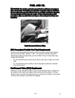
Страница 34: ...n Agency EPA requires portable fuel systems that are produced after January 1 2011 for use with outboard engines to remain fully sealed pressurized up to 34 4 kPa 5 0 psi These tanks may contain the following An air inlet that opens to allow air to enter as the fuel is drawn out of the tank An air outlet that opens vents to the atmosphere if pressure exceeds 34 4 kPa 5 0 psi Fuel Demand Valve FDV ...

Страница 35: ...e tank exceeds 34 4 kPa 5 0 psi A hissing noise may be heard as the tank vents to the atmosphere This is normal The fuel tank includes a fuel demand valve that prevents pressurized fuel from entering the engine and causing a fuel system overflow or possible fuel spillage When installing the fuel tank cap turn the cap to the right until you hear a click This signals that the fuel cap is fully seate...

Страница 36: ...s or sparks in the area while filling fuel tanks Fill the fuel tanks outdoors away from heat sparks and open flames Remove the portable fuel tanks from the boat to fill them Always stop the engine before filling the tanks Do not completely fill the fuel tanks Leave approximately 10 of the tank volume unfilled Fuel will expand in volume as its temperature rises and can leak under pressure if the ta...

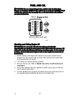
Страница 37: ...ard to vertical not tilted position when checking engine oil For accurate readings check oil only when engine is cold or after engine has not run for at least an hour 1 Before starting cold engine tilt outboard out up past vertical to allow trapped oil to drain back to the oil sump Allow outboard to remain tilted for approximately one minute 2 Tilt outboard to vertical operating position 3 Remove ...

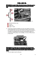
Страница 38: ...l Allow a few minutes for the oil to drain to the oil sump and recheck the dipstick If necessary add additional oil to bring the oil level within the upper 1 3 level of the operating range Avoid overfilling do not try to fill the oil level to the top bar 47404 IMPORTANT Inspect oil for signs of contamination Oil contaminated with water will have a milky color to it oil contaminated with fuel will ...

Страница 39: ...8 Install the oil fill cap hand tight 9 Install the top cowl FUEL AND OIL eng 29 ...

Страница 40: ... to alert the operator of an active problem within the engine s operating system 1 Continuous six second beep Indicates a critical engine condition Depending on the condition the Engine Guardian system may engage and protect the engine by limiting its power You should return to port immediately and contact your servicing dealer 2 Intermittent short beeps for six seconds Indicates a noncritical eng...

Страница 41: ...reducing engine power in order to provide engine protection If Engine Guardian has been activated reduce the engine speed The problem will need to be identified and corrected The system must be reset before the engine will operate at higher speeds Moving the throttle lever back to the idle position will reset the Engine Guardian system If the Engine Guardian system has determined the reset has not...

Страница 42: ...g out or up The term trim generally refers to the adjustment of the outboard within the first 20 range of travel This is the range used while operating the boat on plane The term tilt is generally used when referring to adjusting the outboard further up out of the water With the engine turned off and ignition switch turned on the outboard can be tilted out of the water At low idle speed the outboa...

Страница 43: ...plow with their bow in the water while on plane This can result in an unexpected turn in either direction called bow steering or oversteering if any turn is attempted or if a significant wave is encountered 2 Trimming out or up can Lift the bow higher out of the water Generally increase top speed Increase clearance over submerged objects or a shallow bottom Increase steering torque or pull to the ...

Страница 44: ...board from tilting up during reverse operation Turn out the manual tilt release valve three turns counterclockwise This allows manual tilting of the outboard Tilt the outboard to the desired position and tighten the manual tilt release valve 47663 AUXILIARY TILT SWITCH This switch can be used to tilt the outboard up or down using the power trim system a Auxiliary tilt switch OPERATING IN SHALLOW W...

Страница 45: ...gher steering torque loads The trim tab can compensate for normal steering torque in many cases and can be adjusted within limits to reduce any unequal steering effort 26816 NOTE Trim tab adjustment will have little effect reducing steering torque if the outboard is installed with the antiventilation plate approximately 50 mm 2 in or more above the boat bottom TRIM TAB ADJUSTMENT Operate your boat...

Страница 46: ... for each person aboard and readily accessible it is the law A ring type life buoy or buoyant cushion designed to be thrown to a person in the water Know your boats maximum load capacity Look at the boat capacity plate Fuel supply OK Arrange passengers and load in the boat so the weight is distributed evenly and everyone is seated in a proper seat Tell someone where you are going and when you expe...

Страница 47: ...s tilt the outboard so the gearcase is completely out of water except in freezing temperatures when not in use Wash the outboard exterior and flush out the exhaust outlet of the propeller and gearcase with fresh water after each use Each month spray Mercury Precision or Quicksilver Corrosion Guard on external metal surfaces Do not spray on corrosion control anodes as this will reduce the effective...

Страница 48: ...es to propeller or gear ratio changes Reduces the possibility of detonation Enhances overall reliability and durability of the engine Setting Trim Angle while Running Engine at Idle Speed a Relief hole submerged wrong b Relief hole above waterline correct Operating in Shallow Water When operating your boat in shallow water you can tilt the outboard beyond the maximum trim range to prevent hitting ...

Страница 49: ...ately one minute every ten minutes 2 For the next eight hours of operation avoid continuous operation at full throttle for more than five minutes at a time Starting the Engine Before starting read the Prestarting Check List and Engine Break in Procedure in this section NOTICE Without sufficient cooling water the engine the water pump and other components will overheat and suffer damage Provide a s...

Страница 50: ...yard Stop Switch 19791 5 Shift outboard to neutral N position N 58237 6 Ignition key starting Turn ignition key to the START position and release the key The electronic starting system will automatically crank the engine for starting If the engine fails to start the engine will stop cranking Turn the key to the START position again until engine starts OPERATION 40 eng ...

Страница 51: ...of water flowing out of the water pump indicator hole IMPORTANT If no water is coming out of the water pump indicator hole stop the engine and check the cooling water intake for obstruction No obstruction may indicate a water pump failure or blockage in the cooling system These conditions will cause the engine to overheat Have the outboard checked by your dealer Operating the engine while overheat...

Страница 52: ...resulting in severe engine damage Do not shift the outboard into reverse when the engine is not running Damage to the shift linkage could occur The outboard has three gear shift positions forward F neutral N and reverse R When shifting always stop at the neutral position and allow the engine idle speed to stabilize before shifting into another gear Always shift the outboard into gear with a quick ...

Страница 53: ...ilure Some caustic cleaning chemicals may cause or accelerate corrosion Exercise caution when using cleaning chemicals around the engine and follow the recommendations on the packaging of the cleaning product CLEANING GAUGES IMPORTANT Never use high pressure water to clean gauges Routine cleaning of the gauges is recommended to prevent a buildup of salt and other environmental debris Crystalized s...

Страница 54: ...a mild nonabrasive soap Use a soft clean cloth when washing 3 Dry thoroughly with a soft clean cloth 4 Wax the surface using a nonabrasive automotive polish polish designed for clear coat finishes Remove the applied wax by hand using a clean soft cloth 5 To remove minor scratches use Mercury Marine Cowl Finishing Compound 92 859026K 1 CLEANING CARE FOR THE POWERHEAD SALTWATER USE If the outboard i...

Страница 55: ...IFICATION LABEL An emission certification label showing emission levels and engine specifications directly related to emissions is placed on the engine at the time of manufacture a Idle speed b Engine horsepower c Piston displacement d Engine power kilowatts e Date of manufacture f US EPA engine family name g Regulated emission limit for the engine family h Regulated emission limit for the engine ...

Страница 56: ...and bolts standard boat transom 75 55 3 Outboard mounting locknuts and bolts metal lift plates and setback brackets 122 90 Visually inspect the fuel system for deterioration or leaks Check steering system for binding or loose components Check propeller blades for damage Inspect the hydraulic steering fittings and hoses for leaks or damage if equipped Inspect the hydraulic steering fluid level if e...

Страница 57: ... transom 75 55 3 Outboard mounting locknuts and bolts metal lift plates and setback brackets 122 90 Check corrosion control anodes Check more frequently when used in saltwater Refer to Corrosion Control Anode Drain and replace gearcase lubricant Refer to Gearcase Lubrication Inspect battery Refer to Battery Inspection Saltwater usage Remove and inspect spark plugs for corrosion and replace as nece...

Страница 58: ...ints Replace water pump impeller dealer service 1 Lubricate the splines on the upper driveshaft dealer service Check wiring and connectors dealer service Replace alternator drive belt Refer to Alternator Drive Belt Inspection dealer service Replace the spark plugs BEFORE PERIODS OF STORAGE Refer to Storage section Maintenance Schedule Decal 150 FourStroke The following table shows the icons and a ...

Страница 59: ...em Flush the internal water passages of the outboard with fresh water after each use in salt polluted or muddy water This will help prevent a buildup of deposits from clogging the internal water passages NOTE The outboard can be tilted or in the vertical operating position during flushing 1 With the engine turned off place the outboard in either the operating position vertical or in a tilted posit...

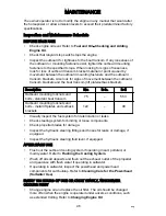
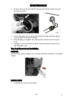
Страница 60: ...t 15 minutes 5 When flushing is complete turn off the water and disconnect the water hose 6 Install the cover on the flush connector Place the flush connector back into the bottom cowl Top Cowl Removal and Installation REMOVAL Unlock the top cowl by pulling out on the rear cowl latch Lift the top cowl off the engine 47632 INSTALLATION 1 Lower the top cowl over the engine MAINTENANCE 50 eng ...

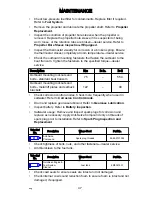
Страница 61: ... to negative 4 Ensure the battery is equipped with a nonconductive shield to prevent accidental shorting of battery terminals Fuel System WARNING Fuel is flammable and explosive Ensure that the key switch is off and the lanyard is positioned so that the engine cannot start Do not smoke or allow sources of spark or open flame in the area while servicing Keep the work area well ventilated and avoid ...

Страница 62: ...essure and should only be serviced by an authorized dealer Removal 1 Turn the ignition key switch to the OFF position 2 Move the lift handle so that the locking tab clears the bracket a Lift handle b Locking tab secured under bracket 3 Use the lift handle and pull the fuel filter out of its opening If necessary move the fuel hose so that it clears the bracket while lifting the fuel filter 4 Push i...

Страница 63: ...f necessary 4 Install the fuel filter back into the opening Position the lift handle so that the locking tab is secured under the bracket Corrosion Control Anode The outboard has corrosion control anodes at different locations An anode helps protect the outboard against galvanic corrosion by sacrificing its metal to be slowly eroded instead of the outboard metals Each anode requires periodic inspe...

Страница 64: ...propeller bore sleeve is designed to enhance engine characteristics and boat performance by minimizing engine exhaust escaping between the outside of the propeller and the gear housing Exhaust gas mixing with the water over the propeller blades will cause a loss of engine and boat performance IMPORTANT An authorized dealer should replace the propeller bore sleeve if it is suspected of being worn l...

Страница 65: ...arting Place a block of wood between the propeller blade and the anti ventilation plate 1 Shift outboard to the neutral N position N 58237 2 Straighten the bent tabs on the propeller nut retainer 3 Place a block of wood between the gearcase and the propeller to hold the propeller and remove the propeller nut 26901 4 Pull the propeller straight off the shaft If the propeller is seized to the shaft ...

Страница 66: ...seizing to the propeller shaft especially in saltwater always apply a coat of the recommended lubricant to the entire propeller shaft at the recommended maintenance intervals and also each time the propeller is removed FLO TORQ II PROPELLERS 1 Install the propeller onto the shaft with the supplied components as shown 2 Place the locknut retainer over the raised pins on the drive sleeve adapter and...

Страница 67: ...sleeve adapter e Locknut retainer f Locknut g Raised pins h Tabs bent against the locknut Description Nm lb in lb ft Propeller nut 75 55 3 FLO TORQ IV PROPELLERS 1 Install the propeller onto the shaft with the supplied components as shown 2 Tighten the locknut to the specified torque 45232 c d e f a b g h MAINTENANCE eng 57 ...

Страница 68: ...washer b Drive sleeve c Propeller d Drive sleeve adapter e Locknut retainer f Locknut g Tabs bent into grooves Description Nm lb in lb ft Propeller nut 75 55 3 Spark Plug Inspection and Replacement 1 Remove the spark plug leads Pull the rubber boots off the spark plugs 47660 c d e f a b g 45248 MAINTENANCE 58 eng ...

Страница 69: ...ous metal is not visible on the spark plug electrode IMPORTANT The color of the plug may not accurately reflect its condition To accurately diagnose a faulty plug inspect the precious metal on the plug s electrode If no precious metal is visible replace the plug a Precious metal 4 Set the spark plug gap Refer to Specifications 27848 a 9381 MAINTENANCE eng 59 ...

Страница 70: ...portion of the ground electrode e When it is necessary to close the gap gently tap the plug ground electrode on a hard surface 5 Saltwater use Apply a thin coating of Anti Seize Compound only on threads of spark plugs Tube Ref No Description Where Used Part No 81 Anti Seize Compound Spark plug threads 92 898101389 6 Before installing spark plugs clean off any dirt on the spark plug seats Install t...

Страница 71: ...e with the same rating a Cover b Spare fuse holders c Fuse holder d Fuse 4 IGN 20 amp ignition system e Fuse 2 FUEL 20 amp fuel delivery f Fuse 1 DIAG 2 amp diagnostics vessel accessory harness g Fuse 3 HELM 15 amp 14 pin remote control harness cowl trim switch h Good fuse i Blown fuse h i 47408 20 20 2 15 a b c d e f g MAINTENANCE eng 61 ...

Страница 72: ...owing conditions are found Cracks in the back of the belt or in the base of the V grooves Excessive wear at the roots of the grooves Rubber portion swollen by oil Belt surfaces roughened Signs of wear on edges or outer surfaces of belt 4 Install the flywheel cover with three screws Tighten the screws to the specified torque Description Nm lb in lb ft Flywheel cover screws 8 71 Lubrication Points 1...

Страница 73: ...for removal and installation of the propeller Coat the entire propeller shaft with lubricant to prevent the propeller hub from corroding and seizing to the shaft 47623 2 Lubricate the following with 2 4 C with PTFE or Extreme Grease Tube Ref No Description Where Used Part No 95 2 4 C with PTFE Steering cable 92 802859A 1 Extreme Grease Steering cable 8M0071842 MAINTENANCE eng 63 ...

Страница 74: ... Fitting b Steering cable end WARNING Incorrect cable lubrication can cause hydraulic lock leading to serious injury or death from loss of boat control Completely retract the end of the steering cable before applying lubricant 3 Lubricate the following with lightweight oil Steering link rod pivot points Lubricate pivot points 47652 b a 47651 MAINTENANCE 64 eng ...

Страница 75: ...ATF Tube Ref No Description Where Used Part No 114 Power Trim and Steering Fluid Power trim reservoir 92 858074K01 47647 Changing Engine Oil ENGINE OIL CAPACITY Engine oil capacity is approximately 6 liter 6 3 US qt IMPORTANT Tilt the outboard out up past vertical for approximately one minute to allow any trapped oil to drain back to the oil sump OIL CHANGING PROCEDURE 1 Tilt the outboard out up p...

Страница 76: ...hten the oil drain valve clockwise and remove the oil drain hose 7 Tighten the oil drain valve to the specified torque Clean up any oil in the valve area Description Nm lb in lb ft Oil drain valve 15 133 IMPORTANT Overtightening the oil drain valve can damage the oil sump a Oil drain valve b Drain hose c Loosen 2 1 2 turns maximum CHANGING OIL FILTER 1 Remove the plug from the oil trough and attac...

Страница 77: ...This will bring the oil level within the midpoint of the operating range 2 Idle engine for five minutes and check for leaks Stop the engine For an accurate oil level reading allow the engine to cool for at least an hour before checking the oil level Refer to Fuel and Oil Checking and Adding Engine Oil NOTE Checking the oil level within five minutes of engine shutdown can falsely read up to 1 liter...

Страница 78: ...l gear wear An excessive amount of metal filings or larger particles chips may indicate abnormal gear wear and should be checked by an authorized dealer DRAINING GEARCASE 1 Place the outboard in a vertical operating position 2 Remove the propeller Refer to Propeller Replacement 3 Place the drain pan below the outboard 4 Remove the vent plug and fill drain plug and drain lubricant a Vent plug b Fil...

Страница 79: ...ars at the vent hole a Vent hole b Fill hole IMPORTANT Replace the sealing washers if damaged 4 Stop adding the lubricant Install the vent plug and sealing washer before removing the lubricant tube 5 Remove the lubricant tube and install cleaned fill drain plug and sealing washer a b 22693 MAINTENANCE eng 69 ...

Страница 80: ...e engine s fuel system other than the fuel tank will remain stable during normal storage periods without the addition of fuel treatment stabilizers Fill the fuel tank and engine fuel system with treated stabilized fuel to help prevent formation of varnish and gum Proceed with the following instructions Portable fuel tank Pour the required amount of Quickstor Fuel Stabilizer follow instructions on ...

Страница 81: ...Install the spark plugs Gearcase Drain and refill the gearcase lubricant refer to Gearcase Lubricant Positioning Outboard for Storage Store outboard in an upright vertical position to allow water to drain out of the outboard NOTICE Storing the outboard in a tilted position can damage the outboard Water trapped in the cooling passages or rain water collected in the propeller exhaust outlet in the g...

Страница 82: ...the engine Fuel tank is empty Fuel tank vent not open or restricted Fuel line is disconnected or kinked Fuel filter is obstructed Refer to Maintenance section Fuel pump failure Fuel tank filter obstructed Ignition system component failure Spark plugs fouled or defective Refer to Maintenance section Engine Runs Erratically POSSIBLE CAUSES Overheating Warning horn not working Low oil pressure Check ...

Страница 83: ...stment or setup Boat overloaded or load improperly distributed Excessive water in bilge Boat bottom is dirty or damaged Battery Will Not Hold Charge POSSIBLE CAUSES Battery connections are loose or corroded Low electrolyte level in battery Worn out or inefficient battery Excessive use of electrical accessories Defective rectifier alternator or voltage regulator Open circuit in the alternator outpu...

Страница 84: ...rs in the recovery of stolen power packages ATTENTION REQUIRED AFTER SUBMERSION 1 Before recovery contact an authorized Mercury dealer 2 After recovery immediate service by an authorized Mercury dealer is required to reduce the possibility of serious engine damage REPLACEMENT SERVICE PARTS WARNING Avoid fire or explosion hazard Electrical ignition and fuel system components on Mercury Marine produ...

Страница 85: ...erial numbers of your power package The name and address of your dealership The nature of the problem CONTACT INFORMATION FOR MERCURY MARINE CUSTOMER SERVICE For assistance call fax or write to the geographic office in your area Please include your daytime telephone number with mail and fax correspondence United States Canada Telephone English 1 920 929 5040 Français 1 905 636 4751 Mercury Marine ...

Страница 86: ...e Before ordering literature have the following information about your power package available Model Serial Number Horsepower Year UNITED STATES AND CANADA For additional literature for your Mercury Marine power package contact your nearest Mercury Marine dealer or contact Mercury Marine Telephone Fax Mail 920 929 5110 USA only 920 929 4894 USA only Mercury Marine Attn Publications Department P O ...

Страница 87: ...s Department W6250 Pioneer Road P O Box 1939 Fond du Lac WI 54936 1939 Ship To Copy this form and print or type This is your shipping label Name Address City State Province ZIP or postal code Country Quantity Item Stock Number Price Total Total Due OWNER SERVICE ASSISTANCE eng 77 ...

Страница 88: ... utilize the outboard mounting hardware will compromise the ability of that hardware to properly and safely secure the outboard to the transom Outboards that require validated mounting hardware will have the following decal on the transom clamp 51965 Accessories Mounted to the Transom Clamp Bracket Mercury Marine has been made aware that certain aftermarket marine accessories such as emergency boa...

Страница 89: ...ESSORY MOUNTING TO THE TRANSOM CLAMP BRACKET After the engine is mounted to the transom or jack plate in accordance with the engine installation instructions it is acceptable to attach an accessory to the boat by use of the unused bolt holes in the transom clamp bracket as shown in Figure 1 The following list provides additional guidelines for mounting accessories to the transom clamp bracket The ...

Страница 90: ...amp bracket Refer to Figure 1 Figure 1 a Minimum clearance 3 175 mm 0 125 in b Edge of accessory bracket c Transom clamp bracket wall d Radius e Engine supplied mounting fasteners f Fasteners supplied by the accessory manufacturer installed through unused engine mounting bracket holes b c d a f 54624 e OUTBOARD INSTALLATION 80 eng ...

Страница 91: ...ecuring the engine to the boat 1 Do not mount an accessory to the transom clamp bracket in an unsupported condition Refer to Figure 2 54625 Figure 2 2 Do not attach an accessory to the boat by use of the engine mounting hardware Refer to Figure 3 Figure 3 a Engine supplied mounting fasteners b Transom clamp bracket c Accessory 53523 a b c OUTBOARD INSTALLATION eng 81 ...

Страница 92: ... disregard this recommendation and install the engine yourself please make sure to read and comply with these instructions Failure to comply with these installation instructions could lead to serious injury or death NOTE Do not install an accessory electric fuel pump onto the fuel system for this engine Boat Horsepower Capacity WARNING Exceeding the boat s maximum horsepower rating can cause serio...

Страница 93: ...in gear Fuel System ACCESSORY ELECTRIC FUEL PUMP IMPORTANT Do not install an accessory electric fuel pump onto the fuel system for this engine AVOIDING FUEL FLOW RESTRICTION IMPORTANT Adding components to the fuel supply system filters valves fittings etc may restrict the fuel flow This may cause engine stalling at low speed and or a lean fuel condition at high RPM that could cause engine damage L...

Страница 94: ...el hose between the fuel tank and the engine b Manual release c Vent water drain holes FUEL TANKS Portable Fuel Tank Select a suitable location in the boat within the engine fuel line length limitations and secure the tank in place Permanent Fuel Tank Permanent fuel tanks should be installed in accordance with industry and federal safety standards which include recommendations applicable to ground...

Страница 95: ...to the outboard is restrictive contains an antisiphon valve or holds a relatively large volume of fuel because of a long fuel supply line or water separating fuel filter If a primer bulb is installed it can be used during the priming event to shorten the amount of time required to start the engine 1 Verify the engine is in a level vertical position 2 Verify the vessel fuel supply line is connected...

Страница 96: ... ignition key cycle until the purged fuel is relatively clear of air bubbles NOTE If the outboard fuel system does not prime within 15 key on events check for leaks in the fuel supply line to the outboard Repair as needed If no leak is found the fuel supply system to the outboard may be too restrictive Correct the condition and try again 7 Remove the fuel pressure gauge 8 Turn the ignition key on ...

Страница 97: ...ine is connected to the outboard fuel system inlet fitting 3 Turn the ignition key on The fuel pumps will run for approximately three to five seconds 4 Turn the ignition key to the start position and release the key The ECM controls the activation of the starter The starter may continue cranking for up to eight seconds NOTE When priming a drained fuel system residual fuel may cause the engine to f...

Страница 98: ...fting Outboard 1 Remove the top cowl 2 Install the lifting base to the flywheel using three bolts Tighten the bolts securely 3 Thread the lifting eye into the lifting base 4 Connect a hoist that has a minimum lift capacity of 450 kg 1000 lb to the lifting eye 5 Lift the outboard and place it on the transom a Lifting base b Lifting eye 18552 a a b a b 47706 OUTBOARD INSTALLATION 88 eng ...

Страница 99: ...g Bracket Removal 1 Remove the two top screws and loosen the two bottom screws 2 Slide the shipping bracket off the bottom screws 3 Tighten the bottom screws to the specified torque a Shipping bracket b Top screws c Bottom screws Description Nm lb in lb ft Bottom screws 7 9 70 c b c a 47720 OUTBOARD INSTALLATION eng 89 ...

Страница 100: ...que 47708 Description Nm lb in lb ft Nut 47 5 35 Steering Link Rod Fasteners if equipped IMPORTANT The steering link rod that connects the steering cable to the engine must be fastened using a special washer head bolt a Part Number 10 856680 and self locking nylon insert locknuts c and d Part Number 11 826709113 These locknuts must never be replaced with common nuts nonlocking as they will work lo...

Страница 101: ...0 b Flat washers c Nylon insert locknut 11 826709113 d Nylon insert locknut 11 826709113 Description Nm lb in lb ft Special washer head bolt 27 20 Nylon insert locknut d 27 20 Nylon insert locknut c Tighten until it seats then back off 1 4 turn Assemble steering link rod to steering cable with two flat washers and nylon insert locknut Tighten locknut until it seats then back nut off 1 4 turn Assem...

Страница 102: ...Determining Recommended Outboard Mounting Height 23 in 24 in 25 in 63 5 cm 60 9 cm 58 4 cm e OUTBOARD INSTALLATION 92 eng ...

Страница 103: ...e exhaust relief hole will stay at least 25 4 mm 1 in above the waterline when the engine is running at idle speed Having the exhaust relief hole above the waterline will prevent exhaust restrictions Exhaust restrictions will result in poor performance at idle 2 Add 12 7 cm 5 in for XL models to the listed outboard mounting heights 3 The mounting height of the outboard must not exceed 63 5 cm 25 i...

Страница 104: ...a Drill guide holes b Transom drilling fixture c Transom centerline Transom Drilling Fixture 91 98234A2 5489 Aids in engine installation by acting as a template for engine mounting holes 2 Drill four 13 5 mm 17 32 in mounting holes 3973 2757 a a b c OUTBOARD INSTALLATION 94 eng ...

Страница 105: ...t washer 0 875 in diameter Available Outboard Mounting Bolts Part Number Description 67755005 20 x 2 50 in long 1 25 in thread 67755006 20 x 3 50 in long 1 25 in thread 814259 20 x 4 00 in long 2 25 in thread 67755 1 20 x 4 50 in long 2 25 in thread 8M0071543 20 x 5 00 in long 3 25 in thread 8M0038370 20 x 5 50 in long 3 25 in thread 67755 2 20 x 6 50 in long 2 75 in thread 8M0028080 20 x 7 50 in ...

Страница 106: ... The boat transom must be strengthened or the load carrying area increased a Transom yielding under bolt torque b Transom cracking under bolt torque Use a dial torque wrench to determine transom strength If the bolt or nut continues to turn without the torque reading on the dial increasing it is an indication that the transom is yielding The load area can be increased by using a larger washer or a...

Страница 107: ... be flat within 3 17 mm 0 125 in No step in the transom mounting surface is allowed The inside transom mounting bolt washer surface must be flat within 3 17 mm 0 125 in a Step not allowed b Gap between transom clamp and boat transom not allowed a b 51817 OUTBOARD INSTALLATION eng 97 ...

Страница 108: ... ensure proper clearance of the transom bracket relief radius area 51867 Installation 1 Apply marine sealer to the shanks of the bolts not to the threads 2 Fasten the outboard with the correct mounting hardware Tighten the locknuts to the specified torque IMPORTANT Ensure that a minimum of two full threads of the mounting bolts extend beyond the locknut after tightening The locknut must be drawn t...

Страница 109: ...875 in flat washer 4 c Nylon insert locknut 4 d 1 500 in flat washer 4 e Marine sealer apply to the shank of the bolts not the threads Description Nm lb in lb ft Outboard mounting locknuts and bolts standard boat transom 75 55 Outboard mounting locknuts and bolts metal lift plates and setback brackets 122 90 a c d c a d 40952 b e OUTBOARD INSTALLATION eng 99 ...

Страница 110: ... the transom bracket Electrical Fuel Hose and Control Cables RIGGING GROMMET Installation IMPORTANT Sufficient slack must exist in wiring harnesses battery cables and hoses that are routed between the rigging grommet and engine attachment points to relieve stress and prevent hoses from being kinked or pinched OUTBOARD INSTALLATION 100 eng ...

Страница 111: ...harness opening f Battery cable opening g Accessory harness opening h Shift cable opening i Fuel hose opening j SmartCraft harness or additional harness opening k Throttle cable opening 2 Fasten the rigging grommet and rigging adapter with two screws Tighten the screws to the specified torque 3 Hold the wiring hoses and cables together with a cable tie a b c d e f g i j k 47374 h OUTBOARD INSTALLA...

Страница 112: ...on Nm lb in lb ft Screws for attaching the rigging adapter 6 53 REMOTE WIRING HARNESS Route the remote 14 pin boat harness through the rigging grommet Connect the remote harness to the 14 pin connector on the engine harness Fasten the harness with the retainer a Remote 14 pin boat harness b Retainer c 14 pin connector a 47753 47717 a b c OUTBOARD INSTALLATION 102 eng ...

Страница 113: ...es If battery cables longer than the factory supplied cables are required the wire gauge size must increase Refer to the following chart for the correct gauge according to the length IMPORTANT Only copper battery cables should be used Do not use aluminum power cables in any marine installation a Wire gauge size b Cable length IMPORTANT The battery cable length specified in the following chart is t...

Страница 114: ...American Wire Gauge AWG Maximum Length Meter Feet 2 0 24 4 m 80 ft Single Outboard a Red sleeve positive b Black sleeve negative c Cranking battery b a c 15496 OUTBOARD INSTALLATION 104 eng ...

Страница 115: ...tive c Ground cable d Cranking battery FUEL HOSE CONNECTION Fasten the remote fuel hose to fitting with a hose clamp Position the hose clamp so that it will not chafe or cut into an adjacent wiring harness NOTICE Inspect the position of the hose clamp to ensure that it will not chafe or cut into the adjacent wiring harnesses a a b b c d d 15497 OUTBOARD INSTALLATION eng 105 ...

Страница 116: ...nstructions provided with the remote control NOTE Install the shift cable to the engine first The shift cable is the first cable to move when the remote control handle is moved out of neutral 1 Position the remote control and outboard into neutral position 2 Center the shift cable anchor pin with the neutral detent alignment mark a Shift cable anchor pin b Neutral detent alignment mark a b 47751 4...

Страница 117: ...tion Slowly return the handle back to the neutral position Place a mark b on the cable against the cable end guide c Make a center mark c midway between marks a and b Align the cable end guide against this center mark when installing the cable to the engine 6098 b c a 4 Fit the shift cable through the rigging grommet 47738 5 Position the remote control into neutral 6 Place the barrel cup into the ...

Страница 118: ...cure the shift cable to the anchor pin with the bow tie clip retainer a Shift cable end guide b Bow tie clip retainer c Center mark d Cable barrel e Barrel cup c d e b a 47743 OUTBOARD INSTALLATION 108 eng ...

Страница 119: ...way from the cable end Repeat steps a and b c Shift remote control into reverse while turning propeller The propeller shaft should be locked in gear If not adjust the barrel away from the cable end Repeat steps a through c d Shift remote control back to neutral The propeller shaft should turn freely without drag If not adjust the barrel closer to the cable end Repeat steps a through d THROTTLE CAB...

Страница 120: ...throttle cable through the rigging grommet 47739 3 Install the throttle cable to the throttle arm with the bow tie clip retainer 4 Adjust the cable barrel so that the installed throttle cable will hold the throttle arm against the idle stop OUTBOARD INSTALLATION 110 eng ...

Страница 121: ...e the cable barrel and barrel cup into the barrel retainer a Bow tie retainer b Throttle cable end guide c Cable barrel d Barrel cup 6 Lock the cable in place with the cable latch a Cable latch b c d 47747 a 47748 a OUTBOARD INSTALLATION eng 111 ...

Страница 122: ...Maintenance Log Record all maintenance performed on your outboard here Be sure to save all work orders and receipts Date Maintenance Performed Engine Hours MAINTENANCE LOG 112 eng ...

Отзывы: