FUEL INJECTION DESCRIPTIONS AND SYSTEM OPERATION
SERVICE MANUAL NUMBER 24
Page 5D-12
90-861327 OCTOBER 1999
Electronic Control Module (ECM) and Sensors
General Description
The MerCruiser Electronic Fuel Injection system is equipped with a computer that provides
the operator with state-of-the-art control of fuel and spark delivery. Computers use voltage
to send and receive information.
Computers and Voltage Signals
Voltage is electrical pressure. Voltage does not flow in circuits. Instead, voltage causes cur-
rent. Current does the real work in electrical circuits. It is current, the flow of electrically
charged particles, that energizes solenoids, closes relays and lights lamps.
Besides causing currents in circuits, voltage can be used as a signal. Voltage signals can
send information by changing levels, changing waveform (shape), or changing the speed
at which the signal switches from one level to another. Computers use voltage signals to
communicate with one another. The different sections inside computers also use voltage
signals to communicate with each other.
There are two kinds of voltage signals, analog and digital. Both of these are used in comput-
er systems. It’s important to understand the difference between them and the different ways
they are used.
Analog Signals
An analog signal is continuously variable. This means that the signal can be any voltage
within a certain range. An analog signal usually gives information about a condition that
changes continuously over a certain range. For example, in a marine engine, temperature
is usually provided by an analog signal. There are two general types of sensors that produce
analog signals: the 3-wire and the 2-wire sensor.
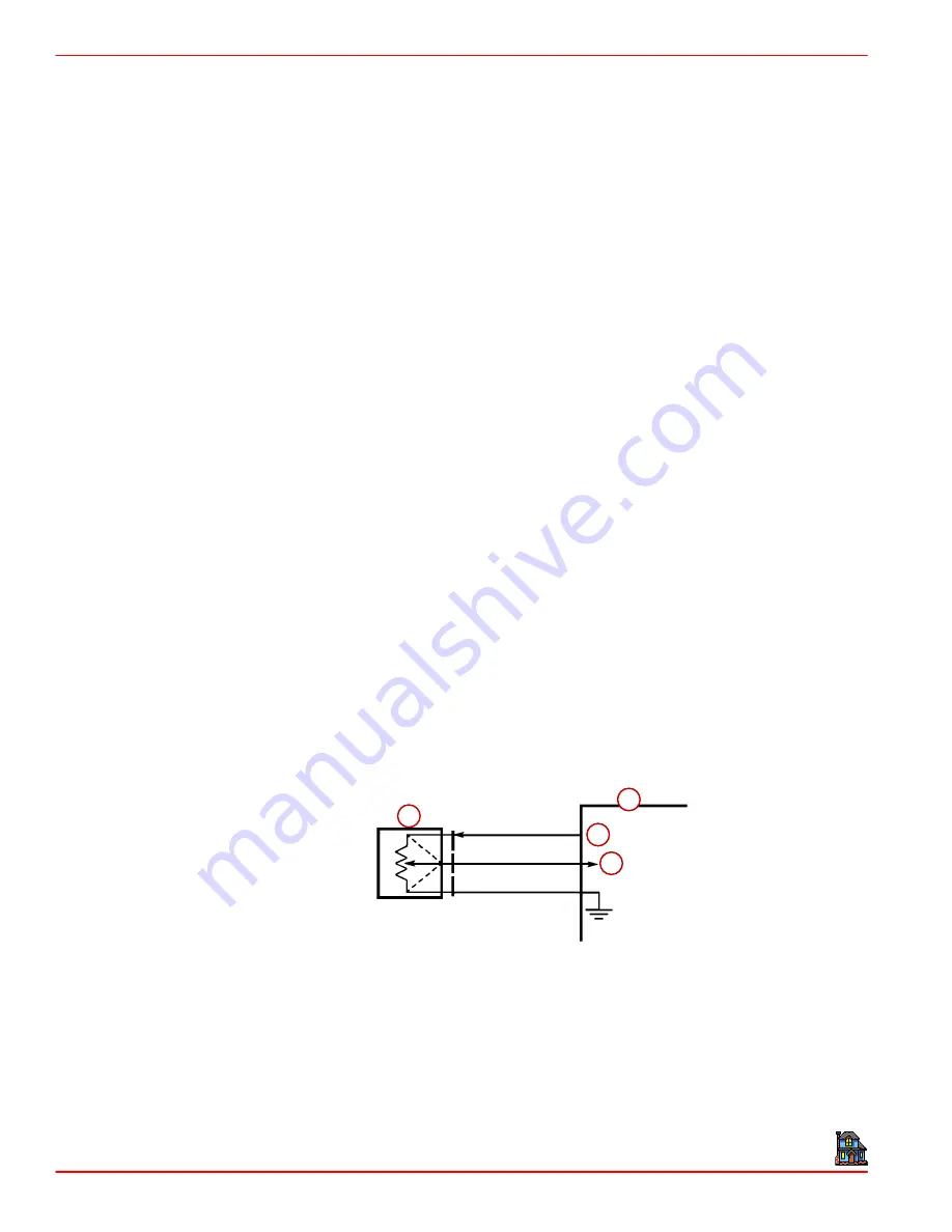
THREE-WIRE SENSORS (MAP AND TP)
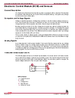
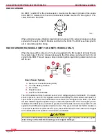
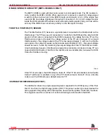
The following figure shows a schematic representation of a 3-wire sensor. All 3-wire sensors
have a reference voltage, a ground and a variable “wiper.” The lead coming off of the wiper
will be the signal to the Engine Control Module (ECM). As this wiper position changes, the
signal voltage returned to the computer also changes.
a
b
c
d
3-Wire Sensor
a -
Typical Sensor
b -
ECM
c -
Voltage Out
d -
Signal Input
e -
Sensor Ground
Index
Содержание 305 CID (5.0L)
Страница 116: ...TROUBLESHOOTING SERVICE MANUAL NUMBER 24 Page 1C 34 90 861327 1 OCTOBER 1999 THIS PAGE IS INTENTIONALLY BLANK Index ...
Страница 142: ...MCM MODELS SERVICE MANUAL NUMBER 24 Page 2A 26 90 861327 1 OCTOBER 1999 THIS PAGE IS INTENTIONALLY BLANK Index ...
Страница 166: ...MIE MODELS SERVICE MANUAL NUMBER 24 Page 2B 24 90 861327 1 OCTOBER 1999 THIS PAGE IS INTENTIONALLY BLANK Index ...
Страница 285: ...STARTING SYSTEM SERVICE MANUAL NUMBER 24 Page 4A 30 90 861327 1 OCTOBER 1999 THIS PAGE IS INTENTIONALLY BLANK Index ...
Страница 315: ...IGNITION SYSTEM SERVICE MANUAL NUMBER 24 Page 4B 30 90 861327 1 OCTOBER 1999 THIS PAGE IS INTENTIONALLY BLANK Index ...
Страница 344: ...CHARGING SYSTEM SERVICE MANUAL NUMBER 24 90 861327 1 OCTOBER 1999 Page 4C 29 THIS PAGE IS INTENTIONALLY BLANK Index ...
Страница 345: ...CHARGING SYSTEM SERVICE MANUAL NUMBER 24 Page 4C 30 90 861327 1 OCTOBER 1999 THIS PAGE IS INTENTIONALLY BLANK Index ...
Страница 364: ...INSTRUMENTATION SERVICE MANUAL NUMBER 24 90 861327 1 OCTOBER 1999 Page 4D 19 THIS PAGE IS INTENTIONALLY BLANK Index ...
Страница 365: ...INSTRUMENTATION SERVICE MANUAL NUMBER 24 Page 4D 20 90 861327 1 OCTOBER 1999 THIS PAGE IS INTENTIONALLY BLANK Index ...
Страница 383: ...MAINTENANCE SERVICE MANUAL NUMBER Page 4E 18 90 861327 1 OCTOBER 1999 THIS PAGE IS INTENTIONALLY BLANK Index ...
Страница 721: ...DIAGNOSTICS SERVICE MANUAL NUMBER 24 Page 5G 94 90 861327 1 OCTOBER 1999 THIS PAGE IS INTENTIONALLY BLANK Index ...
Страница 779: ...GENERAL SERVICE MANUAL NUMBER 24 Page 7A 6 90 861327 1 OCTOBER 1999 THIS PAGE IS INTENTIONALLY BLANK Index ...
Страница 803: ...COLLECTORS SERVICE MANUAL NUMBER 23 Page 7C 16 90 861327 1 OCTOBER 1999 THIS PAGE IS INTENTIONALLY BLANK Index ...
Страница 859: ...HURTH TRANSMISSIONS SERVICE MANUAL NUMBER 24 Page 8C 18 90 861327 1 OCTOBER 1999 THIS PAGE IS INTENTIONALLY BLANK Index ...

