


FOCKE MELER GLUING SOLUTIONS
INSTALLATION
3-6
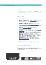
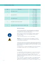
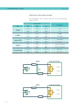
Hose and applicator connection
‘’ series melters/applicators use standard ‘meler’ components. The
entire range of ‘classic’, ‘compact’ and ‘manual’ hoses and applicators may be
connected to this equipment.
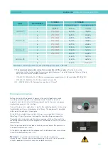
Up to six hose-applicator outputs may be connected to 5, 10, 20 and 35L
‘’ melters/applicators.
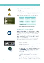
Warning:
When connecting hose-applicator outputs, verify that the connected
power is not above the maximum allowable power for each output.
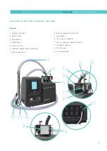
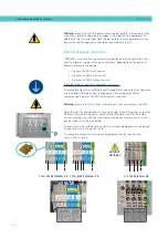
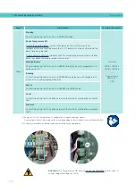
‘’ series melters/applicators are equipped with a six outputs
hydraulic distributors. Connect the hoses to the distributor in order, following
the numbering in the diagram.
Caution:
• In order to identify each hose-applicator, electrically connect them to
the connector with the same number as the output they use.
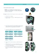
• It is preferable to use couplings at 45° or 90° angle to minimize the
space the hoses occupy. Using straight couplings usually results in
curves with very small radii that may damage the inside of the hose.
• Save the screw-on caps that are removed from the distributor in order
to connect a hose. They may be necessary in the future if a hose is
removed from its location.
• Perform the electrical hose and applicator connections with the
equipment turned off. Failing to do so may result in electrical defects in
the connection and the appearance of alarm messages on the melter/
applicator display.
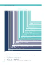
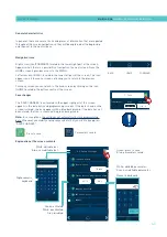
Parameter Programming
Once the melter/applicator and its components are installed, you will need to
program the operational parameters appropriate for the specific application
that will be performed.
Among the various parameters, it is necessary to program the set point
temperature values for each component connected and the value for
overheating warnings. There are two other parameters (weekly start-up and
shut-down programming and the standby temperature value) left to program
in advanced systems, although the factory default values are perfectly valid for
operational purposes.
Chapter “4. MELTER OPERATION” details the operating modes of the machine
and its configuration.
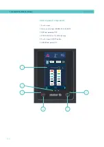
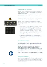
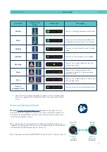
External I/O connections
The input and output (Input/Output) signals enable the melter to communicate
with the main machine simply and directly. Six I/O different signals can be
used, depending on the options installed on the unit. Function of these signals
can be selected by the user
1
2
3
4
5
6
1
2
3
4
5
6
Содержание Micron + 10
Страница 10: ...FOCKE MELER GLUING SOLUTIONS TABLE OF CONTENTS This page is intentionally left blank ...
Страница 38: ...FOCKE MELER GLUING SOLUTIONS INSTALLATION 3 16 This page is intentionally left blank ...
Страница 74: ...FOCKE MELER GLUING SOLUTIONS 4 36 MELTER OPERATION This page is intentionally left blank ...
Страница 84: ...FOCKE MELER GLUING SOLUTIONS 5 10 MAINTENANCE This page is intentionally left blank ...
Страница 90: ...FOCKE MELER GLUING SOLUTIONS 6 6 TECHNICAL CHARACTERISTICS This page is intentionally left blank ...
Страница 91: ...MA 5162 ENG MICRON PISTON ADHESIVE MELTER ELECTRICAL DRAWINGS 7 1 7 ELECTRICAL DRAWINGS ...
Страница 92: ...FOCKE MELER GLUING SOLUTIONS 7 2 ELECTRICAL DRAWINGS This page is intentionally left blank ...
Страница 97: ...MA 5162 ENG MICRON PISTON ADHESIVE MELTER PNEUMATIC DIAGRAM 8 5 Pneumatic diagram for 19 cm3 stroke PUMP ...
Страница 102: ...FOCKE MELER GLUING SOLUTIONS 8 10 PNEUMATIC DIAGRAM This page is intentionally left blank ...
Страница 104: ...FOCKE MELER GLUING SOLUTIONS 9 2 SPARE PARTS LIST This page is intentionally left blank ...
Страница 118: ...This page is intentionally left blank ...