


MA-5162-ENG
PISTON ADHESIVE MELTER
INSTALLATION
3-5
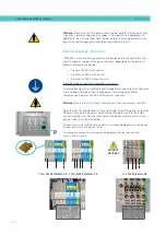
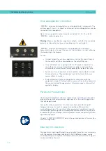
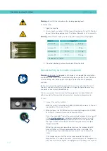
Pneumatic connection
Before connecting the pneumatic power to the melter/applicator, make
sure the pressure regulator is completely closed. To do this, turn the
regulator located on the front of the equipment next to the pressure gauge
counterclockwise as far as it will go.
Connect the plant air supply (max. 6 bar) to the melter/applicator intake using
flexible tubing with an outside diameter of 8 mm. The equipment is provided
with a quick coupling for this purpose.
Activate the air supply to pass and turn the pressure regulator clockwise.
Adjusting to 1 bar of pressure is enough for checking the pump operation.
The pump will not operate and the pressure gauge will show 0 bar until the
melter/applicator and the hoses-applicators connected to it reach the correct
temperature.
Once the pump operation has been checked, you may adjust the pressure to
the operational value you wish.
In the pressure gauge can be found pneumatic and hydraulic pressure values,
the relation between both are 1:13.6.
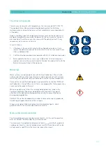
Warning:
Do not exceed a pneumatic pressure of 6 bars under any
circumstances. This may cause severe damage to the unit. Risk of projection
of high-speed particles which may cause significant injury.
(1)
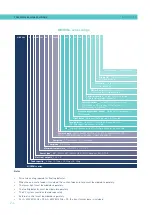
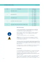
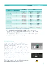
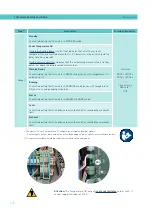
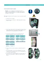
The maximum permissible current for a connection is 27 A per phase.
The table show the
maximum current when using the maximum possible power. Calculate the power to be installed in
each case to choose a suitable connection.
1/N~230V 1~ 50/60Hz + N + PE (Not recommended, except 5. Not available 35)
3/N~400V 3~ 50/60Hz + N + PE (Limited for 35)
(2) 3 ~ 230V 50/60Hz + PE (terminals connection of 10 mm
2
)
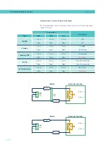
UNIT
No. OUTPUTS
1 PHASE
3 PHASES
230 VAC (
1
)
230 VAC Δ (
2
)
400 VAC Y (
1
)
5
2
25,65 A
18,10 A
10,00 A
4
27,00 A (!)
26,00 A
15,65 A
6
27,00 A (!)
38,90 A
23,48 A
10
2
27,00 A (!)
25,90 A
14,35 A
4
27,00 A (!)
26,00 A
15,65 A
6
27,00 A (!)
38,90 A
23,48 A
20
2
27,00 A (!)
29,80 A
16,52 A
4
27,00 A (!)
29,80 A
16,52 A
6
27,00 A (!)
38,90 A
23,48 A
35
2
-
41,60 A
18,70 A
4
-
41,60 A
26,52 A
6
-
41,60 A
27,00 A (!)
Maximum connection power for each hose/applicator pair: 1,800 W
Содержание Micron + 10
Страница 10: ...FOCKE MELER GLUING SOLUTIONS TABLE OF CONTENTS This page is intentionally left blank ...
Страница 38: ...FOCKE MELER GLUING SOLUTIONS INSTALLATION 3 16 This page is intentionally left blank ...
Страница 74: ...FOCKE MELER GLUING SOLUTIONS 4 36 MELTER OPERATION This page is intentionally left blank ...
Страница 84: ...FOCKE MELER GLUING SOLUTIONS 5 10 MAINTENANCE This page is intentionally left blank ...
Страница 90: ...FOCKE MELER GLUING SOLUTIONS 6 6 TECHNICAL CHARACTERISTICS This page is intentionally left blank ...
Страница 91: ...MA 5162 ENG MICRON PISTON ADHESIVE MELTER ELECTRICAL DRAWINGS 7 1 7 ELECTRICAL DRAWINGS ...
Страница 92: ...FOCKE MELER GLUING SOLUTIONS 7 2 ELECTRICAL DRAWINGS This page is intentionally left blank ...
Страница 97: ...MA 5162 ENG MICRON PISTON ADHESIVE MELTER PNEUMATIC DIAGRAM 8 5 Pneumatic diagram for 19 cm3 stroke PUMP ...
Страница 102: ...FOCKE MELER GLUING SOLUTIONS 8 10 PNEUMATIC DIAGRAM This page is intentionally left blank ...
Страница 104: ...FOCKE MELER GLUING SOLUTIONS 9 2 SPARE PARTS LIST This page is intentionally left blank ...
Страница 118: ...This page is intentionally left blank ...