112 of 271
Thread Feeder Optical Sensor PCB Replacement
The thread feeder optical sensor PCB requires replacement when the sensors are damaged due to im-
proper installation or the sensors become so dirty that they cease to function correctly. It is not expected
that the circuitry on the PCB itself will fail.
Replacement Parts Needed:
• P/N 31292 optical sensor PCB
• P/N 010170-08 two M3x0.5x6mm button head screws (recommend screws be replaced)
Replacement Procedure:
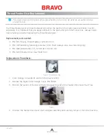
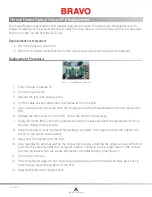
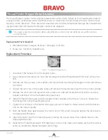
Figure 1 - Thread Feeder Assembly
1. Color change to needle 16.
2. Turn the machine off.
3. Remove the left color change cover.
4. Cut the cable ties and disconnect the harnesses from the PCB.
5. Use a marker and scribe a line onto the housing around the thread feeder PCB, then remove the
PCB.
6. Remove the M3 screws from the PCB. Throw the old M3 screws away.
7. Apply red loctite (MS 222) to the replacement screw threads and install the replacement PCB on
the color change housing loose.
8.
Align the sensor so that the thread feeder flag is centered in the optical sensor and tighten the
screws to the torque specifications.
9. Reconnect the harnesses to the PCB.
10. Use small plastic cable ties and tie the connectors snug by attaching the cable tie around the PCB
such that the cable tie holds the connector in place. Failure to do this might result in the connec-
tors coming loose which can create difficulties in troubleshooting. (See Figure 1.)
11. Turn on the machine.
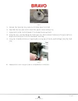
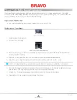
12. If the thread feed gears do not mesh cleanly and quietly with the thread feed drive gear during
color change, adjust the position of the PCB.
13. Reinstall the left color change cover.
Table of Contents
Содержание Bravo
Страница 1: ...Technical Manual Rev 082115 ...


