MeiTrack iButton T1 Скачать руководство пользователя страница 4

MEITRACK T1 User Guide                                                    


Copyright © 2018 Meitrack Group All rights reserved.                                                - 4 - 

1


Copyright and Disclaimer 

Copyright © 2018 MEITRACK. All rights reserved. 

  and 

  are trademarks that belong to Meitrack Group. 

The user manual may be changed without notice.   
Without prior written consent of Meitrack Group, this user manual, or any part thereof, may not be reproduced for 
any purpose whatsoever, or transmitted in any form, either electronically or mechanically, including photocopying and 
recording. 
Meitrack Group shall not be liable for direct, indirect, special, incidental, or consequential damages (including but not 
limited to economic losses, personal injuries, and loss of assets and property) caused by the use, inability, or illegality 
to use the product or documentation. 

2


Product Introduction 

The T1 is a brand new high-end vehicle GPS tracker with market-proven quality and precise positioning. In addition 
to real-time tracking, it supports various peripherals and can be installed into taxies, freight cars, and buses. 

2.1


Product Features 

2.1.1


Harsh Acceleration/Braking Alert and Impact Alert 

You can detect the harsh acceleration/braking alert by setting the limit value. 
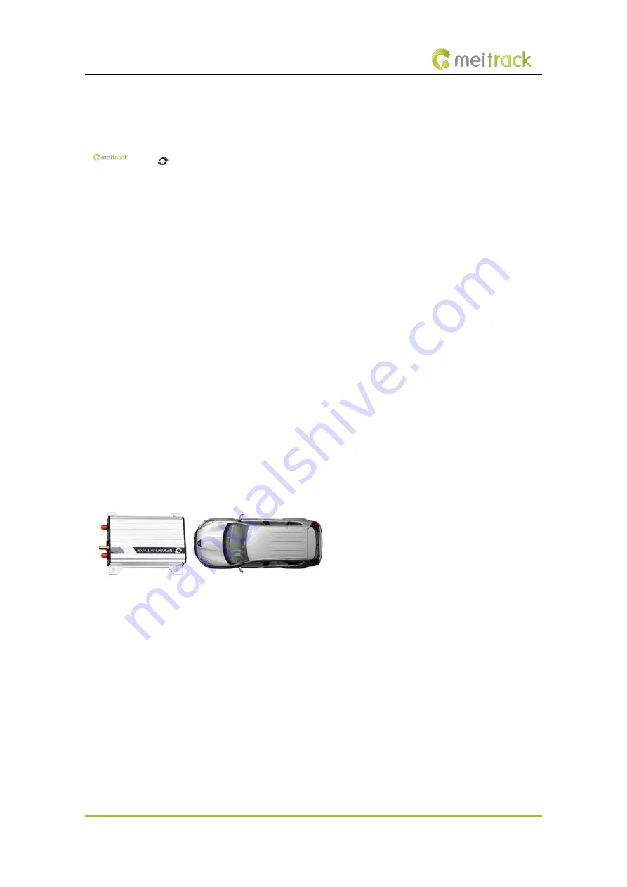
Cautions on device installation: 
1.


The device should be installed into the vehicle according to the following direction. 

2.


The device installation angle cannot exceed 15 degrees. 


The default harsh acceleration and braking alert values are 150 mG and -180 mG respectively. 
Note:   
A.


The alert results vary according to the device installation, vehicle model, vehicle weight, and driving behaviors. 
After the device has been installed properly, you can use the Meitrack Manager software to adjust the harsh 
acceleration and braking alert values by every 10 mG. You can also use the D79 command to set the values. 

B.


Impact  alert  implementation principle is the same as the harsh acceleration and harsh braking, and the 
parameter value is larger. So this alarm event will only occur when the car is driving fast and there is a 
collision at the same time If the car is stopped and hit by other vehicles, it will not occur. 

2.1.2


Roaming Mode 

On the Meitrack Manager page, device parameters in roaming mode differ from that in non-roaming mode. When 
the device detects that it is in roaming mode, it will be operated according to roaming parameters. This helps to 
save network traffic and learn about device working status. 

Содержание iButton T1

Страница 1: ...MEITRACK T1 User Guide MEITRACK T1 User Guide...

Страница 2: ...018 Meitrack Group All rights reserved 2 Change History File Name MEITRACK T1 User Guide Project T1 Creation Date Update Date 2014 06 10 2018 08 02 Subproject User Guide Total Pages 18 Version V2 8 Co...

Страница 3: ...evice 8 6 3 LED Indicator 8 6 4 Configuring Device Parameters by Meitrack Manager 9 6 5 Tracking by Mobile Phone 9 6 6 Common SMS Commands 11 6 6 1 Setting Authorized Phone Numbers A71 11 6 6 2 Settin...

Страница 4: ...You can detect the harsh acceleration braking alert by setting the limit value Cautions on device installation 1 The device should be installed into the vehicle according to the following direction 2...

Страница 5: ...uel power cut off Engine or vehicle door status alert Towing alert Polygonal geo fence alert Fuel stolen alert 3 1 3 Monitoring Harsh braking and Harsh acceleration Idle Recovery Fatigue Driving Speed...

Страница 6: ...rt the vehicle Monitor driver attendance by RFID report LED display Display advertisements and announcements Tire pressure sensor Monitor tire pressure and temperature in real time Ultrasonic fuel lev...

Страница 7: ...to connect a digital temperature sensor or iButton 4 T1 and Accessories T1 and standard accessories T1 with a built in battery External GSM antenna I O cable SOS button External GPS antenna USB cable...

Страница 8: ...lance Ensure that the phone card PIN lock has been closed properly Ensure that the SIM card in the device has subscribed the caller ID service if you want to use your authorized phone number to call t...

Страница 9: ...w to use Meitrack Manager to configure the device on a computer Procedure 1 Install the USB driver and Meitrack Manager 2 Connect the device to a computer by using the USB cable 3 Run Meitrack Manager...

Страница 10: ...current location or the alert type 061314 10 36 Indicates the date and time in MMDDYY hh mm format None V The GPS is invalid A Valid V Invalid 26 Indicates the GSM signal strength Value 1 32 The large...

Страница 11: ...n sequence The tracker will stop dialing when a phone number responds Example Sending 0000 A71 13811111111 13822222222 13833333333 Reply 353358017784062 A71 OK 6 6 2 Setting Listen in Phone Numbers A7...

Страница 12: ...OK 6 6 4 Selecting a Serial Port and Peripheral C70 SMS sending 0000 C70 Serial port selection Peripheral selection SMS reply IMEI C70 OK Description Serial port selection 1 The peripheral port of the...

Страница 13: ...ennas GSM antenna GPS antenna Connect the GSM antenna to the connector which is labeled GSM The GSM antenna is non directional so you can hide it in any place of a vehicle Connect the GPS antenna to t...

Страница 14: ...to an external sensor such as the fuel level sensor 9 Fuel level sensor input Blue and brown Analog input 2 with 12 bit resolution and valid voltage 0 6 6 V The AD cable is equipped with a white plug...

Страница 15: ...ut 3 is connected to the ACC position after the engine is started the platform will read it as ON OFF ON If input 3 is connected to the Start position after the engine is started the platform will rea...

Страница 16: ...rmula is as follows Voltage AD x 3 3 x 2 4096 Pin 9 is connected to the A53 fuel level sensor by default You can install the sensor without calculation formula added on the platform For details see th...

Страница 17: ...peaker Note The RS232 port can be used with either the RFID reader or the camera at a time 8 4 Installing the RFID Reader RS232 Port Pin Number Color Description 1 Red Power output Output voltage 5 V...

Страница 18: ...to the camera To connect T1 to a camera a 4 pin to 8 pin cable is required Connect the device to the 8 pin interface Connect the camera to the 4 pin interface Note The RS232 port can be used with eith...

Отзывы: