Chapter
II
Wiring Installation 5
Full-Digital Control CO2/MAG/MIG Multi-FunctionWelding Machine
2.5.5
Wire SpoolInstallation
1.
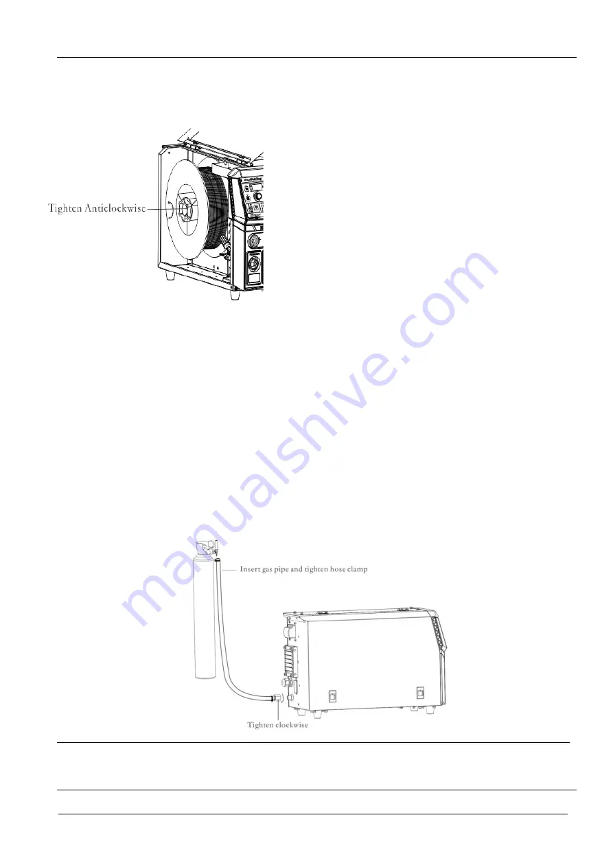
Rotate the end cover of the coil shaft by clockwise direction to loosen
the end cover.
2.
Push in the wire coil;Align the slot of wire coil so that the slot can
successfully enter the terminal of disc shaft. In addition, pay attention to
the rotation direction of wire coil to avoid reverse direction of wire
feeding.
3.
Rotate shaft end cover by anti- clockwise, and lock the wire
feedingcoil.
4.
Select and install the suitable wire feed rollers.
5.
Extract the wire head from the wire coil, cut off the bending part. The
cut welding wirecould notfall into the machine. Straighten the welding
wire about 20cm and check whether there are any sharp corners at the end.
The sharp corners should be filed to avoid the wire feeding tube and
current contact nozzle being damaged.
6.
Pull out a section of welding wire. Go through the slot and leading wire
tube to the welding torch from the rear guide wire. And clamp the wire
feed roll.
7.
Hold the manual wire feeding on the machine panel, then deliver the
welding wire to the torch end. In case of slipping or wire flattening
during wire feeding process, please adjust through pressure adjustment
bar.
.
2.5.6
Regulation on Pressure Adjusting Rod
Regulate the black knob of pressure adjusting rod to make the welding wire equally pass through the wire
feeding liner and contact nozzle to the end of welding torch.Apply certain resistance to the wire reel after
welding wire delivery to preventwire feed roll slipping. If the pressure bar is adjusted too tight, the welding
wire will be flattened, the clad layer on the wire surface will be destroyed, and the service life of feeding
roller will be reduced, which will lead more resistance ,then worse welding instability. Please adjust the
pressing force reasonably.
2.5.7
Air Supply System Connection
Connect the gaspipe to the back panel of the machine, and tighten the hose clamp of gaspipe. Connect the
other end to the gas regulator, and tighten the hose clamp, as shown in Fig. 2-6.
Fig.2- 6Schematic Diagram of Gas Pipe Connection
Attentions:
1.
If any protective gas containing CO
2
is used, please use CO
2
heating pressure reducing valve.
2.
The gas pipes on
welding machine
and gas regulator should be firmlyfixed;otherwise there will be air leakage.


