background image


82 


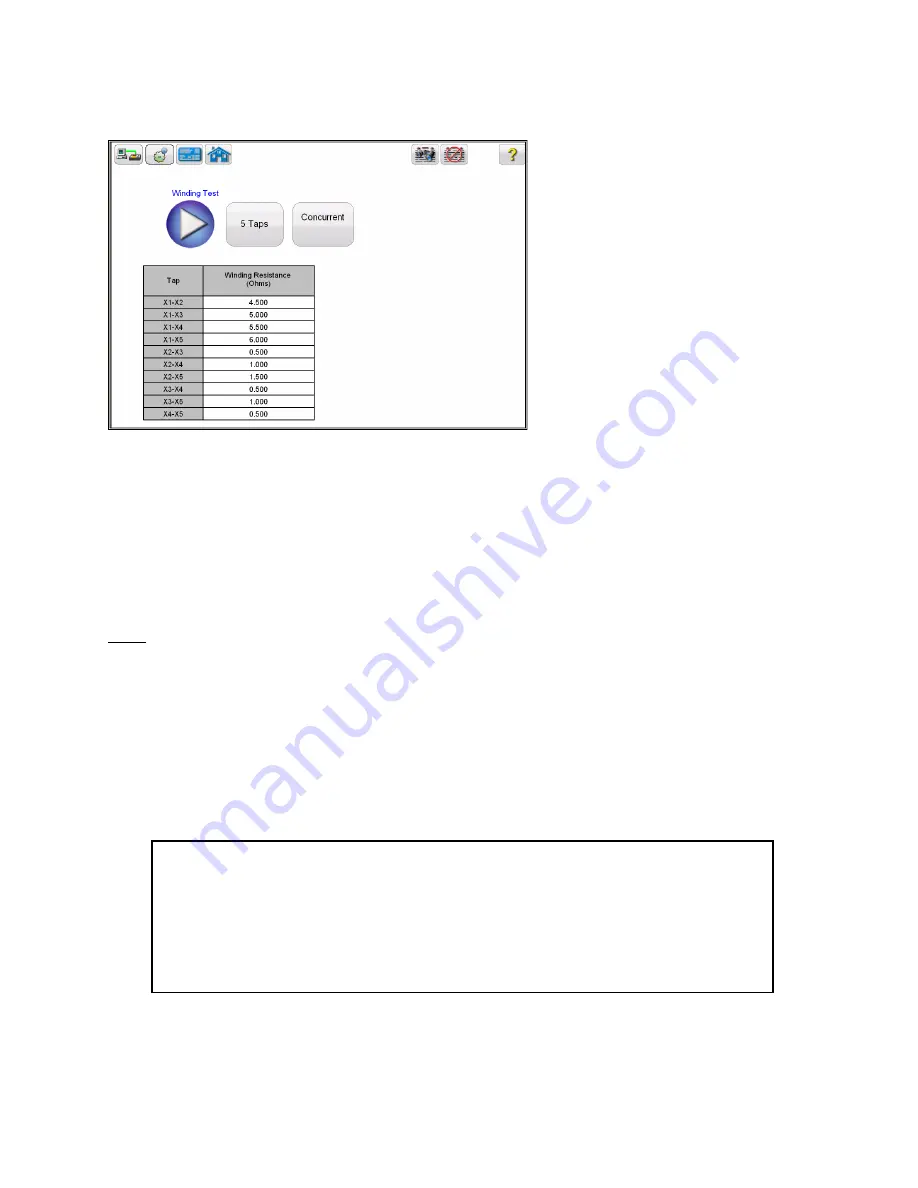
Figure 56:   CT Winding Results - Concurrent 


Winding resistance test is used to determine if the dc resistance of the CT secondary winding is 
within specification or not. A DC current is applied and voltage is measured to determine the 
winding resistance for the selected tap. After measurement winding resistance is displayed in 
digital format on the screen. 


Note:

 A CT should be demagnetized after running the winding resistance test. Run a saturation test to 

demagnetize the CT at the completion of all winding resistance tests. 


9.4.2   Method 2 – Non Concurrent or Testing a Single Tap 

Refer to the safety instructions first before use of the equipment. 

1.


  Verify the Power ON/OFF switch is OFF. Power the test set from a suitable source    
  of power (95-125 or 195-265 V50/60 Hz). 

2.


Connect the ground wing nut to a suitable ground. 


3.


Connect the test set secondary output 

SOURCE

 binding posts 

X1S

 and 

X5S 

to the


secondary of the 

current transformer on the desired tap. 

WARNING 

There is always the possibility of voltages being induced at the terminals of a test 
specimen because of proximity to high voltage energized lines. A residual static voltage 
charge may also be present at these terminals. Ground each terminal to be tested with a 
safety ground stick, before making connections. 


Содержание MRCT

Страница 1: ...1 MEGGER RELAY AND CURRENT TRANSFORMER TEST INSTRUMENT MRCT USER MANUAL February 26 2016 Part 82950R5...

Страница 2: ...government end users The hardware software and documentation are commercial items as that term is defined at 48 C F R 2 101 consisting of commercial computer software and commercial computer software...

Страница 3: ...licable IEC safety markings have been placed on the instrument to notify the operator to refer to the user manual for instructions on correct use or safety related topics Refer to the following table...

Страница 4: ...Misuse of this equipment can be extremely dangerous Always start with the power OFF before connecting the power cord Make sure outputs are off before attempting to make test connections DO NOT attemp...

Страница 5: ...Under no circumstances should the operator put their hand or tools inside the test system chassis area with the test system connected to a power source Lethal voltages are present and may cause serio...

Страница 6: ...et Port 14 3 2 2 USB 2 0 Interface 15 3 3 Smart Touch View Interface 15 3 3 1 STVI Menu Items 19 3 3 1 1 Device Connections 19 3 3 1 2 Device Settings 19 3 3 1 3 Nameplate Information 22 3 3 1 4 Home...

Страница 7: ...57 9 1 Test Plan Creation and Testing of CT 57 9 2 CT Saturation Test 62 9 2 1 Method 1 Concurrent 62 9 2 2 Method 2 Non Concurrent or Testing a Single Tap 66 9 3 CT Ratio Test 69 9 3 1 Method 1 Conc...

Страница 8: ...Figure 21 Customer Information 40 Figure 22 Sample Test Report 41 Figure 23 Sample Mutlitap CT Test Report 43 Figure 24 Ratio and Phase Error Tables 44 Figure 25 Report Configuration 45 Figure 26 View...

Страница 9: ...T Insulation Test Screen 87 Figure 62 CT Insulation Test Connection Diagram 87 Figure 63 CT Insulation Testing Screen 88 Figure 64 CT Insulation Test Results 89 Figure 65 CT Burden Test Screen 90 Figu...

Страница 10: ...ur STVI with the MRCT Test Systems How the unit operates some of the different types of testing you can do and how to save and view your test results with the Smart Touch View Interface software is de...

Страница 11: ...ommunication and control port A USB cable is not provided with the test set or in the optional accessories For control of the SMRT an Ethernet cable is provided since the STVI gets its power over the...

Страница 12: ...Read Only Memory STVI Smart Touch View Interface USB Universal Serial Bus VIGEN Voltage Current Generator Module VRMS Volts Root Mean Square UUT Unit Under Test 1 3 Power Over Ethernet Input Power The...

Страница 13: ...RCT will have an 8 5 inch TFT LCD Color Display this touch panel display provides high resolution and features Wide Viewing Angle Technology with high luminance for reading in direct sunlight The cont...

Страница 14: ...ure the MRCT POWER ON OFF Switch is in the OFF position 0 Plug the unit line cord into an appropriate power source and turn the POWER ON OFF Switch to ON I As the MRCT unit goes through its power up s...

Страница 15: ...also be used to interconnect multiple SMRT units together for synchronous multi phase operation 3 3 Smart Touch View Interface Depending on how the unit was ordered the MRCT can be controlled using t...

Страница 16: ...the Home Screen If the MRCT has an integrated display after powering up the MRCT the user will be brought to the Homes Screen automatically Depending upon how the MRCT was configured the user will se...

Страница 17: ...st screen All individual test screens and settings for the unit can also be accessed from this screen By pressing the navigation buttons on this screen one can select the desired operation Following a...

Страница 18: ...c Relay Saturation Test Ratio Test Winding Resistance Test Insulation Test Burden Test User Help The following are additional user selectable operations if the unit has been configured for VT CVT test...

Страница 19: ...and test data is available View Test Report Delete Test Data File Manager Refer to each menu item below for detailed description 3 3 1 STVI Menu Items 3 3 1 1 Device Connections Selection of Device C...

Страница 20: ...y either ANSI or IEC Ratio Error on Primary Secondary Current Allows user to select whether the ratio error is displayed on Primary Current 101 5 or displayed on Secondary Current 100 4 99 Set Date Ti...

Страница 21: ...s Upgrade Firmware Upgrade firmware for the MRCT or the STVI Display Versions View all Software and hardware versions of the device Logging Enable logging clear all log files or copy log files to USB...

Страница 22: ...mation brings the user to the following screen Figure 9 Name Plate Data Nameplate page is used to fill out the Name plate data of CT under test No of CTs Number of Taps CT Label CT Name Manufacturer B...

Страница 23: ...u to select the CT accuracy class from available options such as aa C10 h T10 b C20 i T20 c C50 j T50 d C100 k T100 e C200 l T200 f C400 m T400 g C800 n T800 VA Burden Buried CT in Delta Connection Th...

Страница 24: ...ate to any test If the MRCT was configured for CT testing only then the following screen will be the Home Screen Figure 10 Home Screen for CT Testing Only Otherwise if the MRCT is also configured for...

Страница 25: ...er by checking the box adjacent to the desired test of the desired tap The various buttons at the bottom of the screen can also be used to easily configure a test Used to auto select Saturation and Ra...

Страница 26: ...1KV and 500V 4 2 Manual Test Selection of the Manual Test Button will bring the user to the following Manual Test Screen Figure 13 Manual Test Screen Within the Manual Test Screen the user has the opt...

Страница 27: ...lay button the MRCT will output the specified current level Ratio Testing To manually test the ratio of a CT the user is required to first select which individual tap is desired Hitting the select tap...

Страница 28: ...y button on the connection diagram After the MRCT has begun to inject voltage the voltage and current readings will be displayed along with the calculated ratio In order to ensure accurate results on...

Страница 29: ...may select the amount of increment the voltgae is either decreased ir increased by turning the knob on the STVI or the up down arrow keys on a laptop After the desired tap selection is made and any ad...

Страница 30: ...e the user has reached a desired voltage a point may be saved by selecting the image of a floppy disk Once the user has generated at least two data points the MRCT will begin to graph the saturation c...

Страница 31: ...by selecting the green CHECK The red X will cancel the operation After selecting to continue the operation the user will be advised that the CT is being demagnetized Figure 1515 Demagnetization Proces...

Страница 32: ...y button While the user can completely test a current transformer from the Run All Tests screen individual tests amy be accessed from the correlating buttons in the drop down list 4 5 Relay Selection...

Страница 33: ...16 Saturation Test Screen Within this screen the user can select between Concurrent and Non concurrent Testing When Concurrent Mode of testing is selected the user is required to select how many taps...

Страница 34: ...g After either selecting the number of taps or the individual tap selection the saturation test is begun by selecting the blue play button 4 7 Ratio Selection of Ratio Test button from the test config...

Страница 35: ...g When Concurrent Mode of testing is selected the user is required to select how many taps is desired to test simultaneously However if the Non Concurrent Mode of testing is selected the user is requi...

Страница 36: ...e blue play button 4 8 Winding Resistance Selection of Winding Resistance Test button from the test configuration screen will bring the user to the following Winding Resistance Test screen Figure 188...

Страница 37: ...o select which individual tap is desired Hitting the select tap button will activate the tap selection dialog After either selecting the number of taps or the individual tap selection the Winding Resi...

Страница 38: ...he user may select the desired test level of either 500V or 1 KV by using the Voltage selection button Each test may be set to a different test voltage The user can also set the same test voltage to a...

Страница 39: ...st the insulation testing is begun by selecting the blue play button 4 10 Burden Selection of Burden Test button from the test configuration screen will bring the user to the following Burden Test scr...

Страница 40: ...ay button 4 11 View CT Report If a test has been run and data is present the View Test Report button will be available Selection of this button will generate a report of all test data for the active C...

Страница 41: ...41 Figure 22 Sample Test Report...

Страница 42: ...alog This will allow the user three options of deleting data Clear test data on screen will only clear the data of the test screen currently active Clear all test data for active CT will the test data...

Страница 43: ...testing results including the data from the following tests excitation ratio phase deviation polarity winding resistance and insulation resistance The MRCT report can also be configured to provide add...

Страница 44: ...ate information CT Type either Metering or Relaying Accuracy Class Burden and or VA Ratio And the user has rand the following tests Saturation Excitation Ratio Winding Resistance Then the Ratio Phase...

Страница 45: ...at the nameplate data can be entered at any time either before the test or after the test has been completed and saved and the Ratio Phase Error button will become available within the report Also ple...

Страница 46: ...nd data is available the user can access this data by selecting the View Data button Selection of the view data button will launch a data viewer that will allow the user to view or copy the data for i...

Страница 47: ...Functions Within the Home Screen selecting the the VT TEST button will cause the button to turn bright yellow This will inform the user that the MRCT is now in VT Testing mode From here the user will...

Страница 48: ...48 Figure 28 VT Testing Mode 5 1 Ratio Selection of Ratio Test button from the home screen will bring the user to the following Ratio Test screen Figure 29 VT Ratio Test Screen...

Страница 49: ...nce the connections are different that when testing CT the MRCT is only capable of test ing VTs one tap at a time After either selecting the number of taps or the individual tap selection the ratio te...

Страница 50: ...ct the number of taps of the VT The default number of taps is two If the user selects more than two taps then the user is also required to select which tap is desired to test If the user selects more...

Страница 51: ...n the secondary winding resistance test is begun by selecting the blue play button 6 0 Functions Available for All Configuration 6 1 File Operations Selection of File Manager brings the user to the fo...

Страница 52: ...order along with date and time stampings Function buttons are used to recall delete or transfer the test results The function buttons are used to manage files as below Used to open file highlighted in...

Страница 53: ...rranty is limited and shall not apply to equipment that has damage or cause of defect due to accident negligence and improper operation faulty installation by the purchaser or improper service or repa...

Страница 54: ...of your unit 2 Go to WWW Megger com 3 Log In If you have not registered before you will need to do so first 4 Go to Software Downloads 5 Click on STVI 6 You will see instructions to enter the serial n...

Страница 55: ...rds are beyond the scope of the basic troubleshooting guide and should be referred to the Service Department at Megger or handled through the Megger Representative If the unit is still within the orig...

Страница 56: ...le Basic troubleshooting of the Ethernet communication cable as follows 1 No power Check power source and line cord If the MRCT powers up but the STVI display does light up check the cable and cable c...

Страница 57: ...Provide the factory with model number Unit serial number nature of the problem or service required return address your name and how to contact you should the factory need to discuss the service reque...

Страница 58: ...T and Xn test set to X3 CT 5 Connect the test set primary binding posts H1 and H2 to CT primary bushings H1 and H2 Observe the polarity marks on the CT H1 on the test set is polarity terminal 6 Turn P...

Страница 59: ...he button This will place a check corresponding to all taps 12 Select the individual taps for Winding Res testing by placing a check in the corresponding box Or select all taps by selecting the button...

Страница 60: ...also be ran at this time by selecting the Blue Play button 17 A connection diagram will appear showing how to properly connect the MRCT to the CT Figure 35 Connection Diagram 5 Tap Concurrent 18 Conti...

Страница 61: ...g Screen Concurrent 20 Test can also be stopped under emergency condition by hitting the Emergency Push to Stop button on the front panel of MRCT Unit will shut off the output voltage 21 After releasi...

Страница 62: ...round 3 Connect the test set secondary output SOURCE binding posts X1S to the secondary of the current transformer X1 and X5S to the secondary of the current transformer on the most external tap WARNI...

Страница 63: ...ry binding posts H1 and H2 to CT primary bushings H1 and H2 Observe the polarity marks on the CT H1 on the test set is polarity terminal 6 Turn Power ON OFF switch to ON 7 After the boot up select the...

Страница 64: ...gs of the secondary X winding while the test is in progress X Current A The MRCT the real time current readings for the secondary X winding while the test is in progress Saturation Curve The excitatio...

Страница 65: ...he Emergency Push to Stop button on the front panel of MRCT Unit will shut off the output voltage 17 After releasing the Emergency Stop Button the test will need to be restarted 18 Upon completion of...

Страница 66: ...t set secondary output binding posts X1 and X5 to secondary of the current transformer on the desired tap Observe the polarity marks on the CT X1 on test set is polarity terminal 5 Connect the test se...

Страница 67: ...on Concurrent 9 Hit the Select Tap function button to select the appropriate tap to be tested 10 Select the tap configuration before hitting the PLAY button If PLAY button is pressed before selecting...

Страница 68: ...Current A The MRCT the real time current readings for the secondary X winding while the test is in progress Saturation Curve The excitation curve is Log Log curve with secondary current on X coordina...

Страница 69: ...y selecting the view report button 18 Saturation points The unit automatically determines the knee point based upon the user selected standard ANSI 30 ANSI 45 or IEC 60044 1 Saturation voltage and sat...

Страница 70: ...rimary bushings H1 and H2 Observe the polarity marks on the CT H1 on the test set is polarity terminal 6 Turn Power ON OFF switch to ON 7 After the boot up select the Nameplate Information menu by sel...

Страница 71: ...diagram will appear showing the proper connections for the MRCT to the CT Figure 46 CT Ratio Connection Diagram Concurrent 12 Check all connections to ensure correctness 13 Hit Blue Play button 14 A...

Страница 72: ...H Voltage V The MRCT the real time voltage readings of the primary H winding while the test is in progress 19 At any point of time Test can be terminated by hitting the ABORT button at the top of the...

Страница 73: ...with polarity The ratio is defined as the number of turns in the secondary as compared to the number of turns in the primary N2 N1 V2 V1 Where N2 and N1 are no of turns of secondary and primary windi...

Страница 74: ...y binding posts H1 and H2 to CT primary bushings H1 and H2 Observe the polarity marks on the CT H1 on the test set is polarity terminal 6 Turn Power ON OFF switch to ON 7 After the boot up in the Home...

Страница 75: ...tap to be tested 10 Select the tap configuration before hitting the PLAY button If PLAY button is pressed before selecting the tap following message will appear 11 After selecting the appropriate tap...

Страница 76: ...g will appear requesting how much Voltage to apply to the CT during the ratio test 15 Enter a voltage 1V and 300V that is less than the knee point of the CT 16 Hit Blue Play button to begin test 17 Th...

Страница 77: ...by hitting the ABORT button at the top of the screen Figure 51 CT Ratio Testing Screen Non Concurrent 19 Test can also be stopped under emergency condition by hitting the Emergency Push to Stop button...

Страница 78: ...n the secondary as compared to the number of turns in the primary N2 N1 V2 V1 Where N2 and N1 are no of turns of secondary and primary windings respectively V2 and V1 are the secondary and primary sid...

Страница 79: ...secondary output binding Xn to the most external secondary of the current transformer For Example on a 3 Tap CT Connect X1 test set to X1 CT X2 test set to X2 CT and Xn test set to X3 CT 5 Turn Power...

Страница 80: ...ill allow the user to test multiple taps in parallel Figure 53 CT Winding Test Screen Concurrent 9 Select the play button and a connection diagram will appear showing the proper connections for the MR...

Страница 81: ...t any point of time Test can be terminated by hitting the ABORT button at the top of the screen Figure 55 CT Winding Test ABORT 13 Test can also be stopped under emergency condition by hitting the Eme...

Страница 82: ...thod 2 Non Concurrent or Testing a Single Tap Refer to the safety instructions first before use of the equipment 1 Verify the Power ON OFF switch is OFF Power the test set from a suitable source of po...

Страница 83: ...t the Concurrent Mode of operation This will allow the user to conduct a winding resistance test upon an individual tap Figure 57 CT Winding Test Screen Non Concurrent 7 Hit the Select Tap function bu...

Страница 84: ...tions to ensure correctness 11 Hit Blue Play button to begin test 12 The Winding Resistance test will begin X Voltage V The MRCT displays the real time voltage readings of the secondary X winding whil...

Страница 85: ...fter releasing the Emergency Stop Button the test will need to be restarted 16 Upon completion of all tests the results will be displayed in the test screen or in a test report Figure 60 CT Winding Re...

Страница 86: ...nect the test set secondary output binding posts X1 and X5 to secondary of the current transformer on the tap of the Outer Winding Observe the polarity marks on the CT X1 on test set is polarity termi...

Страница 87: ...r can select one or any combination of the three test mode a Primary to Secondary b Primary to Ground c Secondary to Ground 19 Select the play button and a connection diagram will appear showing how t...

Страница 88: ...Screen 23 Test can also be stopped under emergency condition by hitting the Emergency Push to Stop button on the front panel of MRCT Unit will shut off the output voltage 24 After releasing the Emerge...

Страница 89: ...output binding posts X1S and X5S to either side of the burden of the CT 5 Connect the test set primary binding posts H1 and H2 to either side of the CT burden and H2 WARNING There is always the possib...

Страница 90: ...utton 7 In the Burden test screen select the appropriate test current of either 1 Amp or 5 Amp based upon secondary current rating of the CT under test Figure 65 CT Burden Test Screen 8 Select the pla...

Страница 91: ...est will begin Voltage V The MRCT displays the real time voltage readings of the burden while the test is in progress Current A The MRCT the real time current readings for the burden while the test is...

Страница 92: ...ompletion of all tests the results will be displayed in the test screen or in a test report Figure 68 CT Burden Test Results Screen Burden test is performed to verify that CT under test is capable of...

Страница 93: ...tion diagram below for more details 4 Connect the test set secondary output binding posts X1S and X5S to either side of the burden of the CT 5 Connect the test set primary binding posts H1 and H2 to e...

Страница 94: ...he user may select the amount of increment the voltgae is either decreased ir increased by turning the knob on the STVI 9 After making this selection select the appropriate tap to be tested 10 Begin t...

Страница 95: ...isplayed on the screen in digital readout form Secondary X Current The secondary current is displayed for user reference to monitor while performing ratio and saturation tests 14 Ramp the voltage up a...

Страница 96: ...osts H1 and H2 to either side of the CT burden and H2 6 Turn Power ON OFF switch to ON 7 After the boot up in the Home Screen select the Demagnetization button 8 A connection diagram will appear showi...

Страница 97: ...nnections are correct 10 Continue with demagnetizing the CT by selecting the Blue Play button CHECK The red X will cancel the operation 11 After selecting to continue the operation the user will be ad...

Страница 98: ...larity marks on the VT X1 on test set is polarity terminal 5 Connect the test set primary binding posts H1 and H2 to the secondary terminals of the voltage transformer Observe the polarity marks on th...

Страница 99: ...he blue play button Otherwise hit the Select Number of Tap functions button to select the appropriate number of taps 10 After selecting the appropriate number of taps use the Winding Selector to selec...

Страница 100: ...uch Voltage to apply to the VT primary during the ratio test 15 Enter a voltage 1V and 300V 16 Hit Blue Play button to begin test 17 The Ratio test will begin Voltage V The MRCT displays the real time...

Страница 101: ...atio Testing Screen 19 Test can also be stopped under emergency condition by hitting the Emergency Push to Stop button on the front panel of MRCT Unit will shut off the output voltage 20 After releasi...

Страница 102: ...ing posts X1 and X5 to desired secondary terminals of the voltage transformer Observe the polarity marks on the CT X1 on test set is polarity terminal 26 Turn Power ON OFF switch to ON 27 After boot u...

Страница 103: ...tton to select the appropriate number of taps 30 After selecting the appropriate number of taps use the Winding Selector to select the appropriate winding to be tested 31 After selecting the appropria...

Страница 104: ...while the test is in progress 35 At any point of time Test can be terminated by hitting the ABORT button at the top of the screen Figure 79 VT Winding Test Screen Abort 36 Test can also be stopped und...

Страница 105: ...the Power ON OFF switch is OFF Power the test set from a suitable source of power 95 125 or 195 265 V50 60 Hz 2 Connect the ground wing nut to a suitable ground WARNING There is always the possibility...

Страница 106: ...Screen select the Self Diagnostic button 5 The following connection diagram will appear Ensure the MRCT is connected properly Figure 81 Self Diagnostic Connection Diagram 6 During the Self Test Secon...

Страница 107: ...07 Figure 82 Self Diagnostic Test Screen 7 After the unit has checked the voltage and current generators and meters are working properly the user will be advised the unit has passed or failed the test...

Страница 108: ...ushing CT s can be tested in a de energized circuit breaker which has been totally isolated from the power system CT secondary leads will normally terminate in the control cabinet Refer to the chart f...

Страница 109: ...X1 X2 H1 H2 Jumpers H1 Bushing Secondary of H1 CT located in control cabinet H1 Bushing H2 Bushing H2 H3 X1 X2 X3 H2 Bushing Secondary of H2 CT located in control cabinet H2 Bushing H3 Bushing H3 H1...

Страница 110: ...CT s can be tested in a de energized circuit breaker which has been totally isolated from the power system CT secondary leads will normally terminate in the control cabinet Refer to the chart on for...

Страница 111: ...s X1 X2 H1 H2 Jumpers X1 Bushing Secondary of X1 CT located in control cabinet X1 Bushing Neutral Bushing H1 H2 H3 X2 Bushing Secondary of X2 CT located in control cabinet X2 Bushing Neutral Bushing H...

Отзывы: